
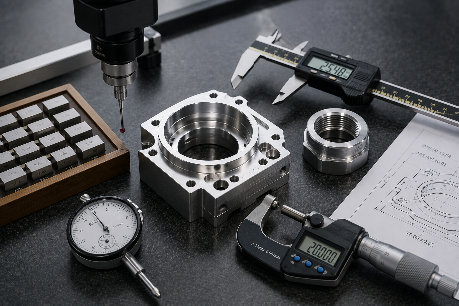
Dimensional inspection proves a machined part matches its drawing. The tools run from a cheap caliper up to a coordinate measuring machine (CMM). Match the tool to the tolerance, that is the whole trick, hand gauges for loose stuff, a CMM when it gets tight or complicated. And it is not one gate at the end. It runs at the first article, mid-run, and final. Below: the tools, when to grab each, and how FAI reports and GD&T keep everything traceable.
A part can measure dead-on at the machine and still flunk on the customer’s bench. Temperature moves it. Tool wear moves it. Fixturing nudges it, and so does the gauge in your hand. I watched a batch sail past the operator’s calipers once, then bounce hard at the customer’s dock, because a caliper just cannot see a ±0.005 mm tolerance that a coordinate machine catches on the first touch. Inspection is how you prove a part is right instead of hoping. Do it well and you catch the mistake cheap, mid-run, not after the crate ships.
What Is Dimensional Inspection in CNC Machining?
So what is it, really? You measure the features, lengths, diameters, angles, positions, and hold them against the print. Tools from a plain micrometer up to a coordinate machine. First article, during the run, at final. All to confirm every critical dimension sits in its band before the part walks out the door.
Boil it to three questions. Is each dimension in tolerance? Do the geometric relationships hold, flatness, position, runout? And is the process even stable, or is part 500 quietly wandering off from part 1? Miss that last one and a batch that started clean ships junk at the end.
What Tools Are Used for Dimensional Inspection?
Now the tools. Calipers and micrometers, everyday work. Height gauges, bore gauges, specific features. The coordinate machine takes the ugly geometry and the tight numbers, down to a micron or two. Optical comparators and profilometers chase profiles and finish. Simple rule: the tighter the tolerance, the harder the job leans on the CMM.
| Ferramenta | Typical Accuracy | Melhor para | Limitation |
| Vernier / digital caliper | ±0,02 mm | General dimensions, quick checks | Too coarse for tight specs |
| Micrometer | ±0,002 mm | Diameters, thickness | One dimension at a time |
| Bore / plug gauge | Go/no-go | Hole size verification | Pass/fail only |
| Height gauge | ±0,01 mm | Step heights, layout | Flat reference needed |
| CMM | ~1-3 µm | Complex geometry, GD&T, tight tol. | Slower, higher cost |
| Optical comparator | ±0,005 mm | Profiles, small features | 2D projection only |
We inspect with CMM, XRF analyzers, and micrometers, and issue FAI reports and RoHS declarations. Anything finished by retificação de precisão, we re-check the diameters on the CMM to confirm the ground surface held size.
When Should You Use a CMM vs Hand Gauges?
Use hand gauges for loose tolerances above about ±0.05 mm and quick checks on the floor. Grab a CMM when the tolerance is tighter than ±0.02 mm, the geometry is complex, there are GD&T callouts like true position, or the part needs a documented report.
When do you actually reach for one over hand tools? Three things decide it. Tolerance first. A caliper cannot honestly sign off a ±0.005 mm feature, and the old rule holds, the gauge should be several times finer than what it checks. Geometry second. True position, profile, angularity between features, that is coordinate data, nothing else hands it to you clean. Traceability third. Aerospace and medical want a documented, repeatable number, and a CMM prints a report where a caliper leaves you a memory.
How GD&T Guides Dimensional Inspection
Then there is the language stacked on top, GD&T. It does more than call out sizes. It defines relationships, flatness, position, concentricity, and it tells the inspector what to measure and off which datum. No more guessing. Two real changes come out of it. One, it pins the datums, so you measure off the surfaces the part actually seats on in the assembly, not some random edge you picked. Two, it controls relationships, not just sizes. A hole can be exactly the right diameter and still land in the wrong spot, and a true-position callout nails that where a plain diameter check shrugs. Cut the whole part in one setup on multi-axis equipment and it gets easier still, one shared reference instead of errors piling up across three fixturings.
First Article Inspection and In-Process Checks
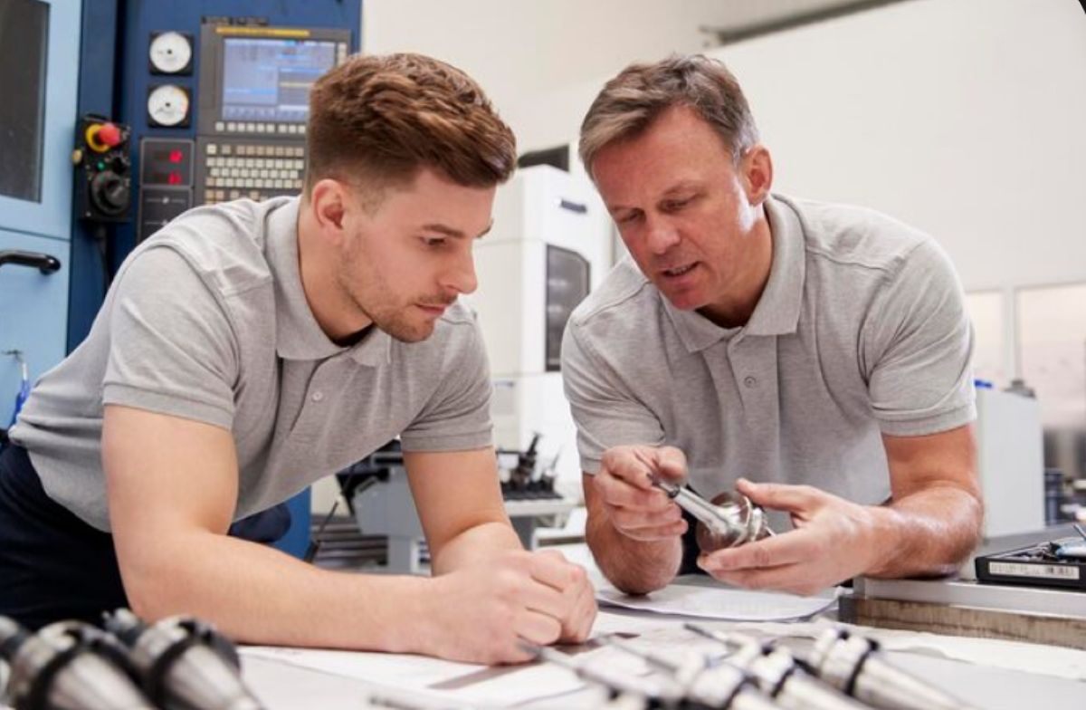
Here is the part people skip. Inspection is not one event at the end. Good shops measure at three points, and each catches a different failure. First article is the big one, a full documented check of the first part off a new setup, proving the program and the fixturing before the run rolls, and that is where most process errors die. In-process checks come next, quick spot measurements that catch tool wear and thermal drift before they shove parts out of band. Final inspection closes it out, sometimes sampled, sometimes a hundred percent on the critical features, before anything gets boxed. Catch it at first article, it costs one part. Catch it at final, it can cost the batch. That gap is exactly why we front-load inspection on every new job. Material plays in too, some materiais de usinagem move after cutting as stress relieves, so we re-check the critical dimensions after any stress-relief step.
The three checkpoints, side by side, and what each one is really there to catch:
| Palco | What It Verifies | Catches | Typical Tooling |
| First Article | Full first part vs drawing | Program and fixturing errors | CMM, FAI report |
| In-Process | Periodic checks during the run | Tool wear, thermal drift | Micrometer, gauges |
| Final | Finished parts (sampled or 100%) | Out-of-spec parts before shipping | CMM, optical comparator |
The Bottom Line on Dimensional Inspection
Strip it down and inspection is how a shop turns should be right into proven right. Match the tool to the tolerance, hand gauges for the loose stuff, a coordinate machine for the tight and the complicated. Let GD&T tell you what to measure and from where. And measure early, since a first-article catch costs one part while a final catch eats the whole batch.
Three things worth asking any supplier before you commit: can they measure to the tolerance you actually need, do they run first-article and in-process checks or just glance at it at the end, and will they hand you a report you can trace.
Need parts with documented dimensional proof, not just a promise? Contact our team for a quote and we will confirm the inspection plan, CMM data, and FAI reporting your application requires before the first part is made.
Perguntas mais frequentes
What is dimensional inspection in CNC machining?
You measure a part’s features, diameters, lengths, angles, positions, and hold them against the drawing tolerances. Tools run from a plain caliper up to a coordinate machine. It happens in three spots, first article, mid-run, final. The whole point is confirming every critical dimension sits in its band before the part ships.
When should I use a CMM instead of hand tools?
When the tolerance is tighter than about ±0.02 mm, the geometry is complex, there are GD&T callouts like true position, or you need a documented, traceable report. Hand gauges cover the loose stuff above ±0.05 mm and quick checks on the floor. The CMM is slower and pricier, so save it for what truly needs the accuracy.
What is a First Article Inspection (FAI) report?
A full, documented measurement of the first part off a new setup. It checks every dimension against the drawing before the rest of the run goes ahead, so an error gets caught on one part, not a whole batch. Aerospace, medical, automotive, they basically require it.
How does GD&T improve inspection accuracy?
It spells out the geometric relationships, flatness, true position, and names the datums to measure from. That strips out the ambiguity plain plus-minus dimensions leave lying around, and it makes sure the inspector checks the features that actually control function, off the surfaces the part really uses.
How accurate does a measuring tool need to be?
Rule of thumb, several times finer than the tolerance it checks, often four to one or ten to one. A caliper reading to ±0.02 mm cannot confirm a ±0.005 mm feature, that is micrometer or CMM work. Match the tool to the tolerance and you dodge both false passes and false rejects.
Does temperature affect dimensional inspection?
More than people think. Metal grows and shrinks with heat, so precise measurement is referenced to a standard 20 degrees C. A hot part straight off the machine reads different from the same part at room temperature, which is why, on tight tolerances, you let it settle before the final CMM check.
Sobre o autor
Escrito pela equipa de engenharia de precisão da Yicen. Our quality engineers bring more than ten years of CMM inspection, GD&T verification, and FAI reporting for aerospace, medical, and automotive customers. Yicen Precision runs 300+ machines in Shenzhen, inspects with CMM and XRF, and holds ISO 9001:2015, ISO 13485, ISO 14001, and IATF 16949 certifications. Explore our Serviços de maquinagem CNC ou contact us for a quote.


 Portuguese
  English
  French
  Spanish
  Japanese
  German