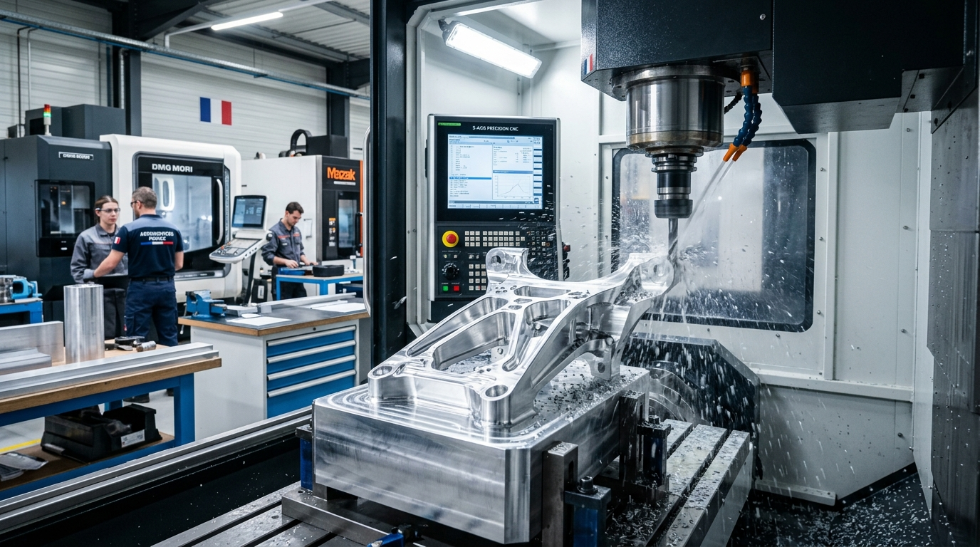

The machined content of a data center used to be modest. Sheet metal chassis, some brackets, a few fan housings. AI hardware changed that, and the reason is heat.
A conventional enterprise rack draws somewhere in the range of 5 to 15 kilowatts. Racks built for AI training workloads now run at densities several times higher, and above roughly 30 to 50 kilowatts per rack, moving that heat with air becomes impractical. The industry response has been direct-to-chip liquid cooling, and liquid cooling is a machined-parts business. Cold plates, distribution manifolds, quick disconnect bodies and sealing interfaces all have to be cut, not stamped or moulded.
This guide covers which data center components are CNC machined, what the thermal requirements do to your tolerances, how copper and aluminum behave differently on the machine, and the design decisions that decide whether a cold plate quotes well or badly.
Which data center components are CNC machined
Not everything in a rack needs machining. The parts that do fall into three groups, and the first is by far the largest.
| Component group | Examples | Typical materials | Why machined |
| Thermal management | Cold plates, heat sinks, vapour chamber lids, thermal spreaders | C110 copper, 6061 and 6063 aluminum | Internal channel geometry and flatness cannot be formed |
| Liquid cooling hardware | Rack and CDU manifolds, quick disconnect bodies, pump housings, fittings | 6061 aluminum, 303 and 316 stainless, brass | Sealing surfaces, ports and leak-tight wetted geometry |
| Structural and electrical | GPU tray frames, rack rails, mounting brackets, busbars, optical module housings | 6061 aluminum, copper, stainless | Tight positional tolerance and fast design iteration |
The pattern worth noticing is that machining is chosen for two different reasons. On thermal parts it is chosen because no other process can produce the geometry. On structural parts it is often chosen because the design is still changing and nobody wants to commit to tooling on hardware that revises every few months.
Cold plates: where most of the precision goes
A direct-to-chip cold plate sits on top of a processor and carries heat away in liquid. Its performance depends on two things a machine shop controls directly: how well the base contacts the die or lid, and how efficiently the internal fin structure transfers heat into the coolant.
Why flatness decides thermal performance
Between the cold plate and the chip sits a thermal interface material. Its job is to fill the microscopic gaps, but it conducts heat far worse than either metal, so the thinner that bond line is, the lower the total thermal resistance. Flatness on the contact face is what controls bond line thickness.
This is why cold plate drawings routinely call out flatness across the contact area far tighter than anything else on the part, commonly in the region of 0.025 mm or better across the die footprint, with surface finish specified around Ra 0.8 micrometres or finer. Those are achievable numbers, but they are not free, and they interact badly with a few common design choices:
- A large plate with a thin base section will distort during machining as stress is released, so flatness must be produced on the finishing pass rather than assumed from the roughing.
- If the plate is brazed, soldered or friction stir welded after machining, heat input moves the base. Flatness has to be specified and produced in the finished condition, which usually means a final skim after joining.
- Applying the same tight flatness across the whole plate rather than the die contact area alone multiplies cost for no thermal benefit.
The general principle is the one that applies to every machined part: tolerance the features that carry a function, and let the rest sit on a sensible general note. Our guide on what designers should know about CNC part tolerances covers how to structure that on a drawing.
Internal fin and channel geometry
The heat transfer surface inside a cold plate is usually a dense array of fins or microchannels. Fin pitch, fin height and channel width set the trade-off between thermal performance and pressure drop, and they also set the machining difficulty. Narrow, deep channels need small diameter cutters running at high aspect ratios, where deflection and tool life become the limiting factors rather than the machine.
Two practical points make a large difference to cost. First, every reduction in channel width forces a smaller cutter and a longer cycle, so channels should be no narrower than the thermal model actually requires. Second, burrs inside coolant channels are a functional defect, not a cosmetic one. Loose particles circulate through the loop and lodge in quick disconnects, pumps and other cold plates downstream. Deburring and cleanliness requirements belong on the drawing, and they should be stated as a requirement rather than left as an assumption.
Machining copper against aluminum for thermal parts
Copper conducts heat roughly two and a half times better than aluminum, which is why high-power cold plates are usually copper while manifolds and lower-power heat sinks are aluminum. The machining behaviour is very different.
| Factor | C110 copper | 6061 aluminum |
| Thermal conductivity | Around 390 W/m.K | Around 167 W/m.K |
| Machining behaviour | Ductile and gummy, prone to built-up edge and burring | Free cutting, excellent chip formation |
| Tooling approach | Sharp high positive rake, polished or uncoated carbide, generous coolant | Standard coated carbide, high speeds |
| Cost driver | Material cost, burr control and finishing time | Mostly cycle time |
| Weight | Heavy, which matters on rack-mounted assemblies | Light |
| Surface protection | Oxidises readily, often nickel plated | Anodised or left bare |
Copper rewards sharp tools and punishes worn ones. A cutter that has started to dull will smear rather than shear, producing rolled burrs on every channel edge and a contact face that will not hold a fine finish. On a fin array with hundreds of edges, that turns into a great deal of manual deburring.
There is also a design trap in mixed metal loops. Copper cold plates plumbed into aluminum manifolds within the same coolant circuit create a galvanic pair, and in the presence of a conductive coolant the aluminum corrodes. Designers handle this with nickel plating on the copper, with corrosion inhibitors in the coolant, or by keeping the wetted path in a single metal family. It is much cheaper to resolve at design review than after a field failure.
If you are still weighing materials, our overview of which alloys to use and how they machine compares machinability and cost across the common engineering metals.
Manifolds, quick disconnects and other wetted parts
Everything downstream of the cold plate has a different failure mode. Thermal parts fail by running hot. Wetted parts fail by leaking, and a leak inside an energised rack is far more expensive than a thermal margin problem.
That shifts the machining priorities:
- Sealing surfaces and O-ring grooves need tight width and depth control, correct surface finish and clean edges. A groove machined slightly shallow will over-compress the seal, and one machined with a sharp lead-in edge can nick it during assembly.
- Port threads must match the specified standard exactly, whether that is NPT, G, SAE straight thread or a metric form. Thread standards are a common source of confusion on international projects, and a tapered thread substituted for a straight one will not seal reliably against an O-ring face.
- Wall thickness around internal drilled passages needs enough material for the working pressure plus a margin, especially where passages intersect.
- Cross-drilled intersections create internal burrs that are difficult to reach. Passage layout should be designed so that every intersection can actually be deburred.
Blind-mate quick disconnect bodies deserve particular attention. They combine tight positional tolerance for alignment during blind insertion with sealing geometry and a pressure boundary in one part, which puts them among the most demanding components in the whole liquid cooling assembly.
Structural hardware, enclosures and busbars
The mechanical parts of an AI rack are less technically demanding per feature but far more numerous. GPU tray frames, mounting rails, standoffs, EMI shielding housings and optical module bodies mostly come down to positional accuracy across hole patterns and a repeatable fit across many units.
Busbars are the exception in this group. They are usually copper, carry very high current, and their machined surfaces matter electrically. Contact faces need flatness and a clean finish because contact resistance generates heat exactly where you do not want it, and edges need to be free of burrs that could compromise clearance or insulation. Plating specification matters here as much as machining.
Enclosure and shielding parts often need cosmetic as well as functional surfaces, since some of this hardware is visible during service. Finish selection should be settled early rather than added at the end, because it affects both dimensions and cost.
Tolerance, finish and inspection expectations
Data center hardware sits between commercial and aerospace expectations. It rarely needs aerospace paperwork, but the thermal and sealing features genuinely need tight control.
| Feature type | Typical requirement | What it controls |
| Cold plate contact face | Flatness in the region of 0.025 mm, Ra 0.8 um or finer | Thermal interface resistance |
| O-ring grooves | Tight width and depth, controlled edge break | Leak integrity |
| Hole patterns and mounting features | Positional tolerance for blind mating and stack-up | Assembly fit across many units |
| General features | Standard general tolerances | Everything not carrying a function |
| Internal channels | Burr-free with a stated cleanliness requirement | Particulate contamination in the loop |
On the inspection side, the sensible baseline is dimensional verification on critical features with a first article report on the initial run, plus pressure or leak testing on any part that will hold coolant. Specify the test method and acceptance criteria on the drawing rather than assuming a supplier will apply the same standard you have in mind.
Finish selection also affects performance rather than only appearance. Plating on copper prevents oxidation and manages galvanic risk, while anodising on aluminum is an insulator and should never be applied to a surface intended to conduct heat or current. Our surface finishing options page sets out what each process does and where it fits.
Do you need 3-axis, 4-axis or 5-axis?
Most data center parts do not need five axes, and specifying them adds cost without adding capability.
- 3-axis milling handles the majority of cold plates, heat sinks, plates and brackets. These are prismatic parts with features on one or two faces, which is exactly what a 3-axis machine does most economically.
- 4-axis is useful for manifolds with ports on several faces, since indexing the part avoids a separate setup and the tolerance error that comes with re-datuming.
- 5-axis earns its cost on compound-angle plenum geometry, complex housings and parts where inter-feature tolerance across multiple faces is critical enough that eliminating setups pays for the machine rate.
The useful discipline is to specify the tolerance and let the shop choose the machine, rather than specifying the machine and hoping the tolerance follows. Our comparison of 5-axis and 3-axis CNC machining explains where that crossover actually falls.
Design choices that lower cost on data center parts
- Restrict tight flatness to the contact footprint. Calling it across the whole plate can multiply the finishing time with no thermal gain.
- Do not make channels narrower than the thermal model requires. Channel width sets cutter diameter, which sets cycle time.
- Use generous internal corner radii. A machined internal corner always carries a radius, and a larger one lets the shop use a stiffer, faster cutter.
- Design passages so intersections can be deburred. If a tool cannot reach a burr, someone will spend a long time trying.
- State flatness in the finished condition when the part is brazed or welded, and allow stock for a final skim.
- Standardise fasteners, threads and port forms across the assembly. Fewer tool changes and fewer thread gauges lower both cost and error rate.
- Send the drawing with the model. The model gives geometry, but only the drawing tells a supplier which dimensions are functional and where inspection should focus.
Prototype to production in a fast-moving hardware cycle
AI hardware iterates quickly. A cold plate design may go through several revisions in the time a conventional product would complete one. That has a practical consequence for sourcing: the ability to turn a revision quickly often matters more than the unit price at the prototype stage, while repeatability and documentation matter more once a design is frozen.
Machining suits both ends of that curve, which is part of why it dominates this hardware category. There is no tooling to re-cut when a revision lands, and the same process scales into low and medium volume production without a change in method. For thermal parts specifically, machining often remains the production process rather than a bridge to something else, because the internal geometry has no cheaper equivalent at these volumes.
Getting a data center component quoted accurately
The most useful thing you can send a supplier is not just the model but the context: which face contacts the die, what pressure the part will hold, which coolant it will see, whether it will be joined after machining, and what volume you expect within twelve months. Those five answers change the process plan more than the geometry does.
Yicen Precision manufactures thermal and mechanical components for electronics and infrastructure hardware from its facility in Shenzhen, running 3-axis, 4-axis and 5-axis milling alongside turning, wire EDM and precision grinding, with tolerances to plus or minus 0.005 mm and CMM inspection with first article reports as standard. You can review our CNC machining services or our custom CNC milling capability for cold plates, manifolds and enclosure hardware, and send a model with your requirements for design-for-manufacturability feedback before anything is cut.
Frequently asked questions
Q: Why are data centers suddenly buying so many machined parts?
A: Rising rack power density has pushed AI hardware from air cooling to direct-to-chip liquid cooling. Cold plates, manifolds and quick disconnect bodies all require machined internal geometry and sealing surfaces that cannot be stamped or moulded.
Q: Should a cold plate be copper or aluminum?
A: Copper conducts heat roughly two and a half times better and suits high-power processors. Aluminum is lighter, cheaper and easier to machine, making it the usual choice for manifolds, lower-power heat sinks and weight-sensitive assemblies.
Q: How flat does a cold plate contact surface need to be?
A: Tighter than most features on the part, commonly around 0.025 mm across the die footprint with a fine surface finish. Flatness controls thermal interface bond line thickness, which drives overall thermal resistance.
Q: Can copper and aluminum share the same coolant loop?
A: Only with precautions. The two form a galvanic pair and the aluminum will corrode in a conductive coolant. Nickel plating the copper, using corrosion inhibitors, or keeping the wetted path in one metal family all address it.
Q: Is machining still used at production volume, or only for prototypes?
A: Both. Structural parts often move to other processes at high volume, but cold plates and manifolds are usually machined in production too, because their internal channel geometry has no cheaper equivalent at these qua