Skip to content
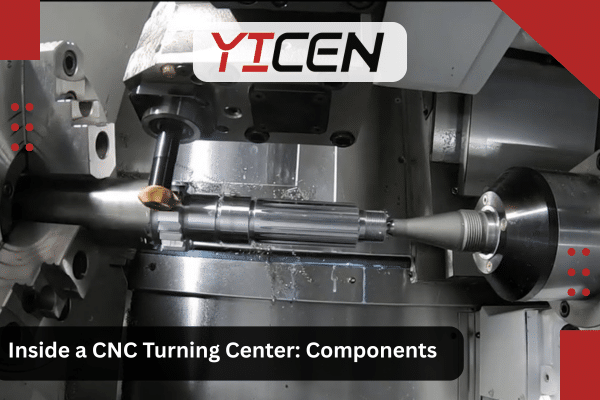
Introduction
Ever wondered what happens inside the machine that shapes perfect round metal parts? A CNC turning center looks simple from the outside, but it’s a high-tech powerhouse. It spins your material fast while sharp tools cut away exactly what you don’t need.
In this guide, you’ll learn what’s inside a CNC turning center. We’ll cover main parts, how everything works together, different types, and real tips to get great results. This matters because good understanding helps you pick the right setup for your project. It cuts waste, saves time, and boosts quality.
The global CNC machining market hit about $26 billion in 2023 and keeps growing fast at around 6-7% each year through 2030 (Grand View Research, 2024). Industries like aerospace rely on these machines for safe, exact parts. Using a trusted CNC turning service makes sure your designs turn into flawless components. Let’s open the door and look inside.
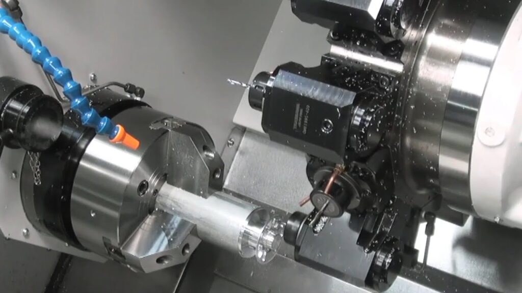
[Suggest image: Labeled cutaway diagram of a modern horizontal CNC turning center showing spindle, turret, chuck, and control panel]
What Is a CNC Turning Center?
A CNC turning center is an advanced computer-controlled lathe. It spins a workpiece while tools cut it into precise shapes like shafts or bushings.
Unlike basic lathes, turning centers do more than just turn. They often mill, drill, and tap in one setup. This saves time and keeps accuracy high.
You get parts with tight tolerances—sometimes within 0.001 inches. That’s why companies in automotive and medical use them daily.
Key Differences: CNC Lathe vs. CNC Turning Center
Many people mix these up. Here’s a clear comparison.
| Feature | CNC Lathe | CNC Turning Center |
| Axes | Usually 2 axes (X and Z) | 3–6+ axes (adds Y, C, live tools) |
| Operations | Mainly turning, facing, threading | Turning + milling, drilling, tapping |
| Tool Changes | Manual or basic turret | Automatic turret with live tooling |
| Best For | Simple round parts | Complex, multi-feature parts |
| Enclosure | Often open | Fully enclosed for safety/chips |
| Production Speed | Good for low-medium volume | High-volume with automation |
Turning centers win for complex jobs because they finish parts faster without moving them.
Main Components Inside a CNC Turning Center
Let’s break down the heart of the machine.
Spindle and Headstock
The spindle spins your workpiece. It’s powered by a strong motor and sits in the headstock.
High-end spindles reach 6,000+ RPM with low vibration. This gives smooth finishes. Precision bearings keep everything true.
Chuck or Workholding System
The chuck grips your raw material tight. Common types include:
- 3-jaw chucks (self-centering for round bars)
- 4-jaw chucks (for odd shapes or off-center work)
- Collets (for small, precise rods)
Quick-change systems let you swap in seconds.
Pro Tip: Always match chuck type to your material shape to avoid slips.
1. Tool Turret
The tool turret is a key component that holds multiple cutting tools for the CNC lathe. It is essentially a rotating holder that allows the machine to switch between different tools rapidly, which is crucial for performing various operations on a single workpiece.
Key Functions:
- Tool Holding Capacity: The turret typically holds between 8 to 24 tools, depending on the machine. This allows the lathe to perform a wide range of operations, such as turning, drilling, boring, threading, and more, without requiring manual tool changes.
- Tool Positioning: The turret rotates, bringing the appropriate tool into position automatically, reducing the need for manual tool changes. This automation significantly increases the machining speed and productivity.
- Live Tooling: Many tool turrets are equipped with live tooling. These are powered tools, driven by small motors that spin the tools (e.g., milling cutters or drills) while the workpiece is rotating. This capability allows the lathe to perform milling or drilling operations in addition to standard turning. This enhances the machine’s versatility, enabling the creation of more complex geometries on the same machine without the need for a separate milling machine.
In short, the tool turret allows for multi-tasking, speeding up the production process by automating tool changes and expanding the range of operations that the CNC lathe can perform.
2. Bed and Ways
The bed is the solid base of the CNC lathe, providing the stability and support needed during machining. The accuracy and rigidity of the bed are critical in ensuring that the machine can hold tight tolerances and maintain consistent performance throughout the machining process.
Key Features:
- Bed: The bed is the foundation that supports all other components of the lathe, including the tool turret, carriage, and tailstock. It is typically made from cast iron or other materials known for their rigidity and ability to absorb vibrations.
- Ways: The ways are smooth, linear rails that guide the movement of the machine’s moving parts, such as the carriage (which holds the tool post) and the tailstock. These ways ensure precision movement and prevent any misalignment during the machining process. The accuracy of the ways directly impacts the overall precision of the workpiece.
- Slant Beds: Many modern CNC lathes feature slant beds, where the bed is tilted at an angle. This slanted design allows chips and coolant to fall away easily from the work area, preventing them from accumulating and causing interference. This helps maintain a clean working environment and reduces the risk of contamination, which can impact accuracy.
Together, the bed and ways ensure the machine’s ability to perform precise and stable machining, contributing significantly to the overall accuracy and longevity of the CNC lathe.
3. Tailstock (When Needed)
The tailstock is an additional component used primarily when machining long or slender parts. Its function is to support the part at its far end, preventing unwanted bending or vibration during the turning process. It is particularly useful when dealing with parts that are prone to deflection, which can negatively impact the accuracy and surface finish of the part.
Key Features:
- Support for Long Parts: The tailstock holds the far end of the workpiece, ensuring that it remains aligned and stable during machining. Without the tailstock, long parts may experience bending or chatter, leading to inaccuracies.
- Live Centers: Many tailstocks come equipped with live centers, which rotate with the workpiece. The live center reduces friction and heat buildup at the point of contact, ensuring smoother rotation and reducing wear on the tailstock itself. Live centers also improve the stability of the workpiece, further enhancing part accuracy.
In summary, the tailstock is crucial for supporting long parts, maintaining rigidity and precision during machining, and preventing deflection that could compromise the final part’s quality.
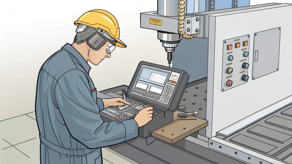
4. Control Panel and CNC System
The control panel is the “brain” of the CNC lathe. It houses the CNC system (often from brands like Fanuc, Siemens, or Haas), which controls every aspect of the machining process based on the provided G-code programs.
Key Features:
- CNC System: The CNC system is the computer that interprets the G-code programs and translates them into specific commands for the machine. These instructions dictate every movement of the machine, from the speed and direction of the spindle to the position of the tool turret and the feed rate.
- Touchscreen Interface: Modern CNC machines typically feature a touchscreen control panel, which makes the system more user-friendly and intuitive to operate. Operators can easily input commands, monitor machine performance, and make adjustments as necessary.
- G-Code Programming: G-code is the standard language used to program CNC machines. It contains a set of instructions that tells the machine exactly what to do, including tool movements, speeds, feeds, and other operational parameters. The control panel allows operators to load and run these programs, guiding the machine through every step of the manufacturing process.
The control panel and CNC system are essential for the automation of the CNC lathe, allowing it to run continuously and produce parts with consistent quality and precision. They also provide operators with the tools to monitor and adjust the process as needed.
How a CNC Turning Center Works Step by Step
- Load your program into the control.
- Secure the workpiece in the chuck.
- Set tools in the turret.
- Start the spindle—it spins the part.
- Tools move along X (across) and Z (length) axes.
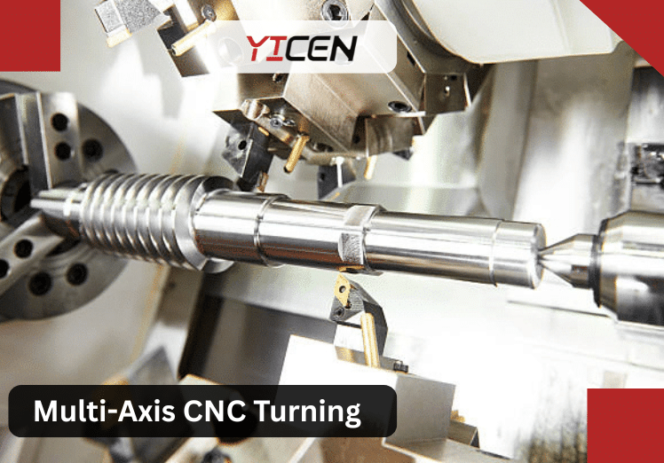
- For advanced centers, Y-axis adds side cuts; C-axis rotates the part for milling.
- Coolant flows to keep things cool and clear chips.
- Sensors watch for issues; machine stops if needed.
- Finished part ejects or you remove it.
The whole process runs automatically after setup.
Types of CNC Turning Centers
Different needs call for different machines.
- Horizontal Turning Centers — Most common. Great for everyday parts. Good chip flow.
- Vertical Turning Centers — Best for big, heavy discs like wheels or rings. Gravity helps hold steady.
- Swiss-Type Turning Centers — For tiny, precise parts like medical screws. Guide bushing supports close to cut.
- Multi-Tasking / Mill-Turn Centers — Combine turning with full milling. Often have dual spindles.
Choose based on part size, complexity, and volume.
Common Operations You Can Do Inside a Turning Center – In-Depth Exploration
Modern CNC turning centers are multi-tasking powerhouses. With live tooling, extra axes (like Y and C), and automatic tool changers, they perform many operations in one setup. This slashes setup time, reduces errors from moving parts between machines, and boosts efficiency—often finishing complex parts 30–50% faster than basic lathes.
Here’s a deep dive into each operation you listed: what it is, how it works, key techniques, tools used, typical applications, challenges, and pro tips.
Facing — Flatten the End
- What it is and how it works
Facing creates a flat, perpendicular surface on the end of the workpiece. The tool moves radially (X-axis) across the spinning part while the Z-axis feeds in slightly.
Key techniques
- Use a facing tool or right-hand turning insert with positive rake.
- Light depth of cut (0.010–0.050 inches) for finish; heavier for roughing.
- Often first operation after chucking to square the face.
- Tools
Carbide inserts (CNMG or WNMG style) with chip breakers.
- Applications
Prepares ends for drilling, threading, or accurate length reference. Common on shafts, fittings, and bushings in automotive and medical.
- Challenges
Built-up edge on soft materials; chatter on large diameters.
Pro Tip: Face with coolant on and a light finishing pass at higher RPM for mirror finish. Always face both ends if using tailstock.
OD Turning — Shape the Outside Diameter
- What it is and how it works
OD (outer diameter) turning reduces the workpiece’s external diameter to precise size and shape—straight, tapered, contoured, or stepped.
Key techniques
- Rough turning: Heavy cuts, high feed (0.010–0.020 IPR), lower RPM.
- Finish turning: Light cuts (0.005–0.015 inches), higher RPM, positive inserts.
- Contour turning uses interpolated X/Z moves for profiles.
- Tools
Turning inserts (CNMG, DNMG, WNMG); grooving tools for necks.
- Applications
Shafts, pins, rollers in aerospace (turbine shafts), automotive (axles), and medical (implants).
- Challenges
Deflection on long parts → use tailstock or steady rests. Heat buildup in tough alloys.
Expert Advice: Use constant surface speed (G96) for consistent chip load and finish across diameters.
Boring — Enlarge Inside Holes
- What it is and how it works
Boring enlarges or finishes existing holes with high accuracy. The boring bar reaches inside while the part spins.
Key techniques
- Rough boring: Step cuts to remove stock.
- Finish boring: Single light pass for size and finish.
- Use anti-vibration bars for deep holes.
- Tools
Boring bars with indexable inserts; adjustable heads for fine tuning.
- Applications
Engine blocks, hydraulic fittings, bearing housings—critical in automotive and oil & gas.
- Challenges
Tool deflection causes taper; vibration in deep bores.
Pro Tip: Use through-spindle coolant and damped boring bars to reach L/D ratios >6 without chatter.
Drilling/Tapping — Make Threaded Holes with Live Tools
- What it is and how it works
Live tooling spins end mills, drills, or taps while the part rotates (or indexes via C-axis). Drill holes axially or radially; tap for threads.
Key techniques
- Peck drilling to clear chips.
- Rigid tapping (synchronized spindle reversal) or tension/compression tapping.
- Off-center holes use Y-axis + live tool.
- Tools
Carbide drills, thread mills, or taps; live tool holders.
- Applications
Flanges, connectors, valve bodies—saves second ops in aerospace and medical.
- Challenges
Chip evacuation in deep holes; tap breakage if sync fails.
Expert Advice: Use thread milling for tough materials or large threads—it’s more forgiving and gives better finish than single-point threading.
Grooving/Parting — Cut Slots or Separate Parts
- What it is and how it works
Grooving cuts narrow channels; parting severs the finished part from the bar stock.
Key techniques
- Grooving: Plunge or side feed; use peck cycles for deep grooves.
- Parting: Full-depth plunge with coolant; angled inserts reduce burrs.
- Tools
Groove/parting inserts (wide range of widths); cutoff tools.
- Applications
O-ring grooves, snap-ring slots, bar feed parting in high-volume automotive.
- Challenges
Burrs, chatter, or insert breakage in parting.
Pro Tip: Use Y-axis grooving for wider slots and better chip control; part off with spindle stopped for cleaner cuts.
Threading — Add Precise Threads
- What it is and how it works
Single-point threading cuts external or internal threads with synchronized feed and spindle rotation.
Key techniques
- Multiple passes: Rough to finish depth.
- Infeed angles: 29–30° for better chip flow.
- Use G76 cycle for automatic multi-pass.
- Tools
Threading inserts (full profile or partial); laydown style.
- Applications
Bolts, fittings, lead screws—vital in automotive, aerospace, and medical.
- Challenges
Poor chip control causes bird-nesting; pitch errors from sync issues.
Expert Advice: Use constant surface speed and chip-breaking infeed for deep threads; verify with thread gauges.
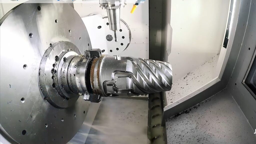
Milling — Flat Surfaces or Pockets with Live Tools
- What it is and how it works
Live tools spin cutters while the part indexes (C-axis) or moves (Y-axis) for flats, hexes, slots, or pockets.
Key techniques
- Face milling for flats; end milling for pockets.
- Polar coordinate programming for complex features.
- Use trochoidal paths for efficient material removal.
- Tools
End mills, face mills, ball mills in live holders.
- Applications
Drive flats on shafts, wrench flats, keyways—common in automotive and robotics.
- Challenges
Vibration from tool length; chip recutting.
Pro Tip: Combine with main spindle turning for true one-setup parts—reduces tolerance stack-up dramatically.
Overall Benefit Summary – In-Depth
These operations shine because turning centers complete parts in one chucking:
- High precision — Tolerances ±0.0005 inches or better; no transfer errors.
- Faster batches — Reduced setups; cycle times drop 40–60% with live tooling.
- Less waste — Exact cuts minimize scrap; better material use.
- Safer enclosure — Full guarding contains chips/coolant.
- Complex shapes — Mill-turn capability handles features once needing multiple machines.
In 2025, automation like bar feeders, robots, and lights-out running is standard in many shops—boosting 24/7 output and cutting labor costs by 20–50% (industry reports show 35% cycle time reductions with automation).
How to Choose the Right CNC Turning Center – Deeper Guide
Ask these expanded questions to match machine to needs:
- Part sizes & materials? Check max turning diameter, length, weight, through-spindle bore, and spindle power/torque for tough alloys (e.g., titanium needs high torque).
- Feature complexity? Need Y-axis for off-center milling? Live tooling? Sub-spindle for back-working? Multi-turret for speed?
- Production volume? Low-mix/high-volume → bar feeder + automation. High-mix/low-volume → quick-change tooling and easy programming.
- Automation add-ons? Robot tending, parts catcher, conveyor, or lights-out package for unattended runs.
- Budget for machine + extras? Factor training, tooling, maintenance, and local service support.
Quick Decision Framework (2025 Trends)
- Simple shafts → 2-axis horizontal.
- Complex mill-turn parts → 4–6+ axis with live tools/Y-axis.
- Large/heavy discs → Vertical turning center.
- High-precision tiny parts → Swiss-type.
- Look for adaptive controls, AI monitoring, and Industry 4.0 connectivity for future-proofing.
Choosing wisely ensures reliability, scalability, and ROI—especially for demanding industries like aerospace, automotive, and medical. If you’re unsure, a reputable CNC turning service can prototype on
Look for brands like Haas, DMG Mori, or Mazak with good local support.
| Factor | Entry-Level Choice | Advanced Choice |
| Axes | 2–3 | 4–6+ |
| Spindle Speed | Up to 4,000 RPM | 6,000+ RPM |
| Live Tooling | No | Yes |
| Cost Range (approx) | $80K–$150K | $200K+ |
| Best For | Simple shafts | Complex aerospace/medical parts |
Common Mistakes to Avoid When Using Turning Centers – In-Depth Guide
Running a CNC turning center efficiently requires attention to detail. Small oversights lead to vibration, poor surface finish, broken tools, machine damage, crashes, or scrapped parts. Below, we explore each of the five common mistakes you listed in depth: explaining why they happen, their real consequences, root causes, warning signs, and detailed solutions/prevention steps. We’ll also expand on the quick reference checklist with deeper explanations and practical tips.
1. Wrong Workholding – Causes Vibration or Slips
- Why it happens and root causes
Workholding (chuck, collet, or fixture) secures the workpiece. If mismatched, under-clamped, unbalanced, or worn, the part shifts, wobbles, or flies out during high RPM.
- Common triggers: Using a 3-jaw chuck on irregular stock (needs 4-jaw), worn jaws losing grip, excessive overhang (long part sticking far out), no tailstock support on slender bars, or ignoring centrifugal force at high speeds.
- Warning signs: Audible chatter, visible runout on dial indicator, part slipping during test spin, or marks/scratches on gripped area.
Real consequences
- Vibration → chatter marks, dimensional errors, poor finish.
- Slip → tool crash, damaged insert, ruined workpiece, safety hazard (flying part).
- In high-volume automotive turning, this causes frequent downtime and rework.
Solutions and prevention
- Match holding method: 3-jaw for round centered bars; 4-jaw or soft jaws for odd shapes; collets for precision small diameters.
- Balance chuck + workpiece (especially at >3,000 RPM).
- Use drawbar force monitoring or torque wrenches for consistent clamping pressure.
- Minimize overhang; add tailstock or steady rests for L/D >4–6.
- Clean jaws regularly; replace when worn (check with feeler gauge).
- Pro Tip: Always perform a low-RPM test spin and watch for wobble before full speed.
2. Skipping Coolant – Leads to Poor Finish and Short Tool Life
- Why it happens and root causes
Operators skip or reduce coolant to “save time/mess” or because nozzles are misaligned/blocked. Coolant removes heat, lubricates, flushes chips, and prevents built-up edge.
- Triggers: Clogged nozzles, low tank level, wrong concentration, using air blast only on aluminum (which needs flood for chip clearing), or high-speed dry turning without proper tooling.
- Warning signs: Dark burn marks, blue discoloration on chips/tool, smoke, short tool life (inserts last 1/3 normal), rough surface with tearing.
Real consequences
- Overheating → thermal expansion → out-of-tolerance parts (especially long shafts).
- Built-up edge → poor finish, dimensional drift.
- Tool wear accelerates 2–5×; inserts chip or fracture.
- In medical or aerospace, heat-affected zones weaken parts or cause cracks.
Solutions and prevention
- Use flood/high-pressure coolant matched to material (soluble oil for steel, mist for titanium).
- Position nozzles close to cut zone; use through-tool coolant for deep holes.
- Maintain concentration (refractometer daily); clean tank weekly to remove tramp oil/chips.
- Monitor pH (8.5–9.0) and bacteria; add biocide if needed.
- Expert Advice: For high-speed finishing (>4,000 SFM), some shops use minimum quantity lubrication (MQL) or vortex cold air—but test first; flood is still safest for most turning.
3. Overloading Tools – Breaks Inserts Fast
- Why it happens and root causes
Pushing too much material removal per pass: high feed rate, deep cut, wrong insert grade/geometry, or dull tools.
- Triggers: Aggressive feeds/speeds to “speed up cycle,” ignoring material hardness, using general-purpose insert on tough alloys (stainless, titanium), excessive tool overhang, or no chip breaker.
- Warning signs: Loud squealing, vibration, insert chipping/cracking, blue/hot chips, short insert life (<30–60 minutes).
Real consequences
- Sudden insert failure → tool crash, gouged workpiece, damaged turret.
- Downtime for tool change; higher consumable costs.
- In production, one broken insert per shift adds up to thousands in lost time yearly.
Solutions and prevention
- Follow manufacturer chip-load recommendations (e.g., 0.008–0.020 IPR for finishing).
- Use positive-rake, chip-breaker inserts; coated grades (TiAlN for heat resistance).
- Step down depth of cut on roughing; use multiple light passes.
- Keep overhang <4× tool diameter; use rigid holders.
- Monitor tool life with software alarms or visual checks.
- Pro Tip: Run conservative first part (80% feed/speed), then ramp up while watching load meter.
4. Ignoring Maintenance – Wears Spindles and Ways
- Why it happens and root causes
Skipping scheduled checks because “it’s running fine” or time pressure. Dust, chips, coolant leaks, and lack of lubrication accumulate.
- Triggers: No daily wipe-down, clogged filters, low lube levels, ignoring unusual noises, or delaying bearing/spindle service.
- Warning signs: Spindle growl, axis drift, lost accuracy, coolant leaks, chips in ways, overheating.
Real consequences
- Spindle bearings fail → costly rebuild ($10K–$50K+).
- Ways wear → backlash, taper errors, poor repeatability.
- Sudden breakdowns halt production for days/weeks.
Solutions and prevention
- Daily: Wipe ways, check coolant/lube levels, clean chip tray.
- Weekly: Inspect spindle runout, grease fittings, change filters.
- Monthly: Align tailstock, check belt tension, test axis backlash.
- Annual: Full spindle/bearing inspection; coolant flush.
- Use PM software or checklists; train operators.
- Expert Advice: Document every check—helps spot trends early (e.g., rising temperature = impending bearing issue).
5. Poor Programming – Creates Crashes or Bad Parts
- Why it happens and root causes
Errors in G-code: wrong offsets, unsafe rapid moves, missing safety lines, incorrect tool nose radius comp, or no simulation.
- Triggers: Manual editing without verification, copy-paste old programs, ignoring machine limits, wrong coordinate system, or skipping dry runs.
- Warning signs: Unexpected rapid moves, tool gouges air/part, alarms during cycle, bad dimensions on first piece.
Real consequences
- Crashes → broken tools, damaged chuck/spindle, scrapped fixtures.
- Bad parts → rework or scrap; delays delivery.
- In worst cases, machine damage requires weeks offline.
Solutions and prevention
- Always simulate graphically (in CAM or control) before running.
- Use proven templates with safe start/end blocks.
- Verify tool offsets with touch probe or manual check.
- Run dry cycle (no part, spindle off) to watch path.
- Add safe retracts and clearance moves.
- Pro Tip: Use single-block mode for first run; watch feed override closely.
Expanded Quick Reference Checklist for Setup
Follow this step-by-step before every job:
- Check material and size match machine limits — Confirm bar diameter, length, weight vs. chuck/spindle capacity. Oversize stock causes imbalance.
- Balance chuck and workpiece — Spin at low RPM; adjust jaws or add weights if needed. Critical above 2,000 RPM.
- Load sharp tools and offsets — Inspect inserts for chips; set tool offsets accurately (use presetter or probe). Wrong offset = crash.
- Set safe home position — Ensure machine returns to a clear, repeatable zero. Prevents collisions on startup.
- Run dry cycle (no part) to test path — Watch full program at reduced speed/feed override. Catch errors early.
- Add coolant and chip conveyor — Fill tank, prime pump, position nozzles, turn on conveyor. Prevents overheating/chip buildup.
- Measure first part before full run — Use micrometer/CMM on key features after first piece. Adjust offsets if off.
Mastering these avoids 80–90% of common issues. Consistent habits and checklists turn potential disasters into smooth production. For complex or high-precision jobs in aerospace, automotive, or medical, consider partnering with an experienced CNC turning service that follows rigorous protocols.
Key Takeaways
- A CNC turning center spins the part while tools cut precisely.
- Main parts include spindle, chuck, turret, bed, and control.
- Advanced types add live tooling and extra axes for milling.
- Benefits: accuracy, speed, less waste, multi-operations.
- Choose based on part needs—horizontal for most, vertical for big items.
- Avoid mistakes with good setup and maintenance.
- Modern centers boost efficiency in growing markets.
Conclusion
Inside a CNC turning center, you’ll find smart design: powerful spindle, quick turret, precise controls, and often extra features like live tools. These work together to make accurate round parts fast and reliably.
Understanding the components and types helps you get better results—whether you run the machine or outsource. Focus on right setup, maintenance, and programming to avoid issues.
For demanding work in aerospace, automotive, or medical, precision matters most. These centers deliver it consistently.
FAQs
1. What is the main difference between a CNC lathe and a turning center?
A basic CNC lathe handles simple turning with 2 axes. A turning center adds more axes, live tools for milling/drilling, and often enclosures. It does complex parts in one setup, saving time
2.Why do some turning centers have live tooling?
Live tooling lets tools spin while the part turns. This adds milling, drilling, or tapping without moving the part. It’s great for parts needing flats or holes at angles, like in automotive fittings.
3.How does a vertical turning center differ from a horizontal one?
Horizontal is common and good for most parts with easy chip removal. Vertical holds big, heavy parts upright—gravity helps stability. Use vertical for large wheels or rings in energy or aerospace.
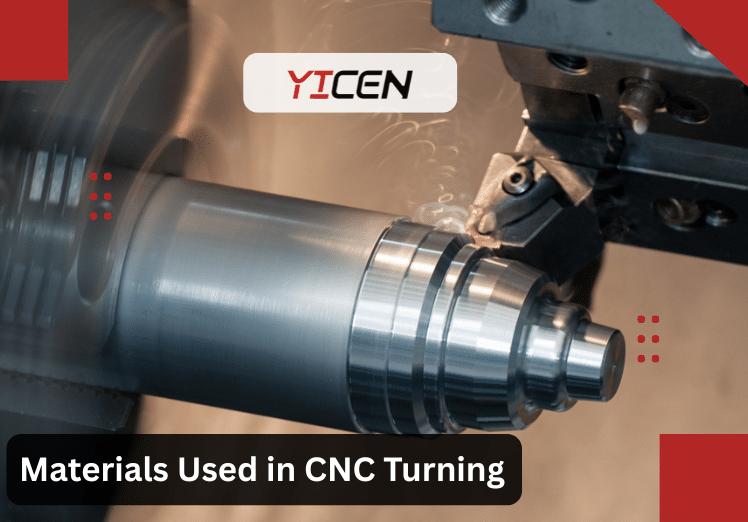
4.What materials work best in a CNC turning center?
Metals like aluminum, steel, titanium, brass, plus plastics and composites. Choose based on your industry—titanium for aerospace strength, aluminum for lightweight automotive parts.
5.How accurate can a CNC turning center get?
Most hold tolerances of ±0.0005 inches or better. High-end ones reach ±0.0001 inches with good setup. This precision suits medical implants or aerospace engine parts.