Saltar para o conteúdo
Rapid prototyping converts a CAD file into a physical part fast — from 24 hours to 7 days depending on process, complexity, and material. The right process depends on four variables: what the prototype needs to prove (geometry, fit, function, or regulatory compliance), what material properties it needs to simulate, what tolerances are required, and what it costs relative to the value of the information it generates. This guide covers every major rapid prototyping process with engineering-level specs, tolerance tables, material compatibility matrices, cost breakdowns, and a structured process selection framework.
Prototyping decisions made on instinct are expensive. Teams default to the process they used last time, or the one their supplier promotes, or the one that’s fastest to quote. They end up with FDM plastic parts being used to validate assembly fits that require metal, or CNC machined prototypes for geometry checks that could have been done in SLA at one-fifth the cost.
The wrong process doesn’t just waste money. It wastes iteration time — which in competitive product development is a more expensive resource than the prototype itself.
This guide gives you the engineering framework to choose correctly. Every major process, every relevant spec table, every DFM rule that changes what’s achievable at each stage of development.
Em Precisão Yicen, we run CNC machining, 3D printing, and sheet metal fabrication for prototypes from quantity 1, with lead times starting at 24 hours. The process selection framework in this guide is the same one we use when a buyer uploads a file and asks what process fits their program.
What Is Rapid Prototyping — and What Isn’t It?
Rapid prototyping is the production of physical parts directly from CAD data, at a speed that allows meaningful design iteration within a development cycle. The “rapid” qualifier is relative to production processes like injection molding, die casting, or stamping — where tooling lead times run 4–16 weeks and design changes require tooling modifications at significant cost.
With rapid prototyping, the same 5-axis CNC machining center or SLS printer that made your part today can make a dimensionally different version tomorrow, from a revised CAD file, with no tooling change.
What rapid prototyping is not: a substitute for production-intent parts in all situations. Prototypes validate design intent. They are not always made from production materials, on production tooling, at production quality standards. Knowing which stage of prototype fidelity you need at each point in the development cycle is the core skill this guide develops.
The Five Stages of Prototype Development
Most products move through five distinct prototype stages. Each stage has different fidelity requirements, which map to different processes and costs.
| Stage | Purpose | Required Fidelity | Typical Process |
| Concept Model | Communicate design intent, early feedback | Geometry only | FDM, SLA |
| Form and Fit Prototype | Verify dimensional fit in assembly | Dimensional accuracy, geometry | SLA, SLS, CNC |
| Functional Prototype | Test mechanical performance under load | True material properties, tolerances | CNC machining, Metal 3D printing |
| Pre-Production Prototype | Validate manufacturing process and quality | Production-equivalent material and process | CNC machining, Vacuum casting |
| Pilot Run | Validate production process at low volume | Full production standards | Injection molding, CNC, Sheet metal |
Teams that skip from concept to functional prototype without the intermediate form/fit stage pay for it in functional prototype revisions. Teams that stay in concept prototyping too long delay the discovery of fit and tolerance problems that only surface in physical assemblies.
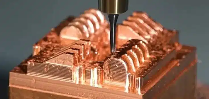
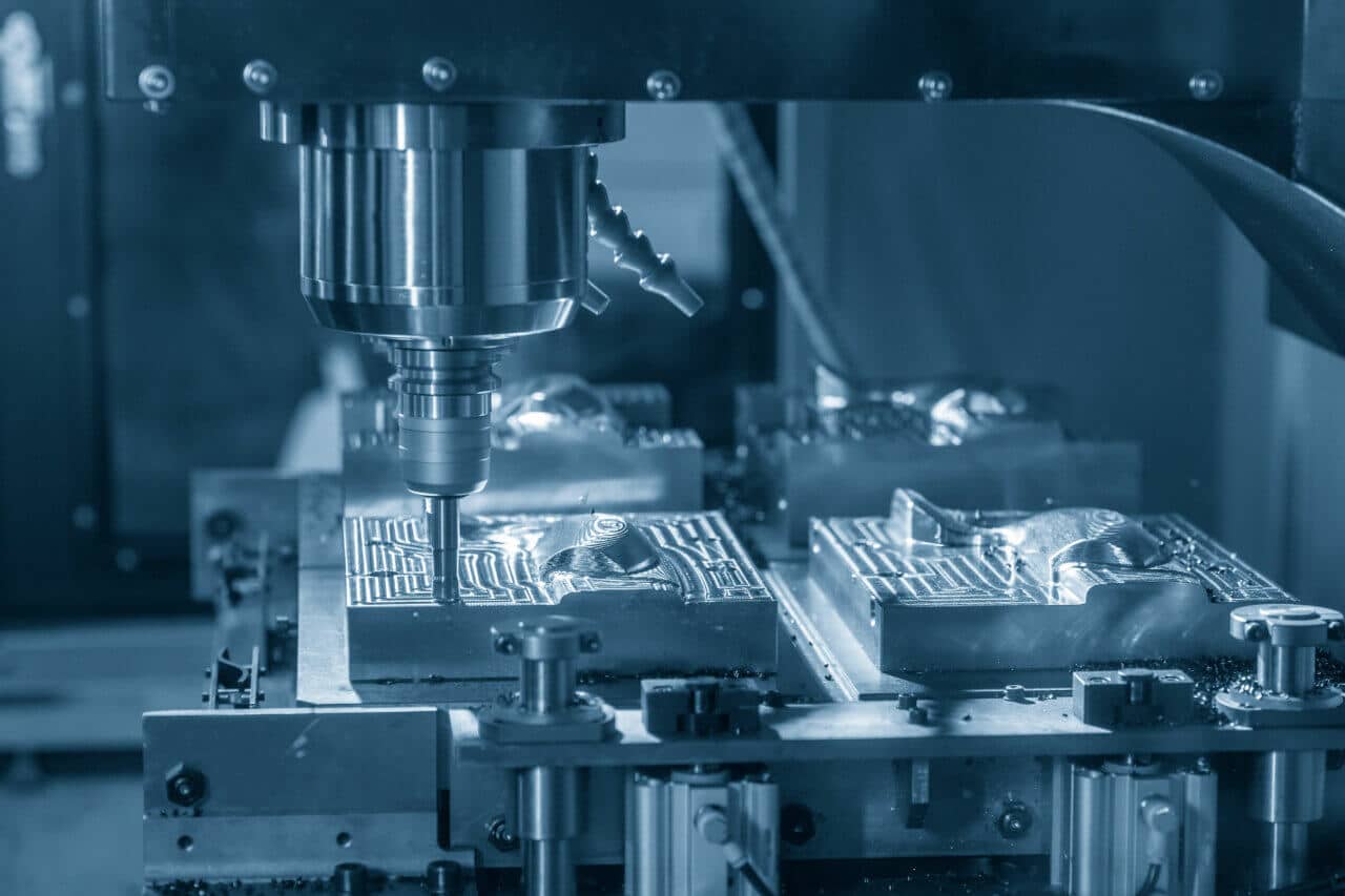
Process 1: CNC Machining
CNC machining is the highest-fidelity rapid prototyping process for metal and structural plastic parts. It removes material from a solid billet using computer-controlled cutting tools, producing parts with true bulk material properties, tight tolerances, and finished surfaces.
CNC Prototyping Capabilities
| Parâmetro | Standard CNC | Precision CNC | 5-Axis CNC |
| Dimensional tolerance | ±0,05 mm | ±0,01 mm | ±0,01 mm |
| Surface finish (as-machined) | Ra 1.6–3.2 µm | Ra 0.8 µm | Ra 0.8 µm |
| Min. internal corner radius | 0.5 mm (tool dependent) | 0.3 mm | 0.3 mm |
| Min. wall thickness (metal) | 0,75 mm | 0,5 mm | 0,5 mm |
| Min. wall thickness (plastic) | 1.0 mm | 0.8 mm | 0.8 mm |
| Max. depth-to-width ratio (slots) | 4:1 | 6:1 | 6:1 |
| Lead time (simple parts) | 3–5 days | 5–7 days | 5–10 days |
| Lead time (Yicen Precision) | 24–72 hours | 3–5 days | 3-7 dias |
Materials Available for CNC Prototyping
Metais:
| Material | Resistência à tração | Maquinabilidade | Typical Use Cases |
| Aluminum 6061-T6 | 310 MPa | Excelente | Structural brackets, housings, prototypes |
| Aluminum 7075-T6 | 572 MPa | Bom | High-stress aerospace/automotive parts |
| Stainless Steel 303 | 620 MPa | Bom | Corrosion-resistant functional parts |
| Aço inoxidável 316L | 515 MPa | Moderado | Medical, marine, chemical applications |
| Mild Steel (A36/1018) | 400 MPa | Excelente | Structural prototypes, fixtures |
| Alloy Steel 4140 | 655 MPa | Moderado | High-strength shafts, gears |
| Titanium Grade 5 (Ti-6Al-4V) | 950 MPa | Difícil | Aerospace, medical implant prototypes |
| Brass C360 | 385 MPa | Excelente | Electrical connectors, fittings |
| Copper C101 | 220 MPa | Bom | Heat exchangers, electrical components |
Plásticos de engenharia:
| Material | Resistência à tração | Temp Resistance | Propriedades principais |
| Delrin (POM) | 70 MPa | 100°C continuous | Low friction, dimensional stability |
| PEEK | 100 MPa | 250°C continuous | Chemical resistance, biocompatible |
| Nylon PA6/PA66 | 75–85 MPa | 100°C continuous | Impact resistance, fatigue resistance |
| Policarbonato (PC) | 55–75 MPa | 120°C continuous | Optical clarity, impact resistance |
| PTFE | 25 MPa | 260°C continuous | Non-stick, chemical inertness |
| ABS | 40–50 MPa | 80°C continuous | General purpose, paintable |
| PEAD | 26–33 MPa | 80°C continuous | Chemical resistance, food contact |
| Acetal Copolymer | 65 MPa | 90°C continuous | Precision gears, bearings |
When CNC Is the Right Prototyping Process
CNC machining is the correct choice when: the prototype will undergo functional testing under mechanical load, dimensional tolerances tighter than ±0.1 mm are required, material properties must match production intent, surface finish matters functionally (sealing surfaces, bearing seats, mating faces), or the part geometry is machinable (no extreme internal features inaccessible to cutting tools).
CNC is overkill when: the prototype is for geometry visualization only, no structural loading will occur, and dimensional accuracy to ±0.5 mm is sufficient. In those cases, SLA or SLS is faster and cheaper.
Process 2: SLA (Stereolithography)
SLA cures liquid photopolymer resin layer-by-layer using a UV laser. It produces the smoothest surface finish of any additive process and the highest dimensional accuracy in the 3D printing category. It’s the correct process for fine-feature geometry validation, appearance models, and master patterns for vacuum casting.
SLA Capabilities
| Parâmetro | Value |
| Precisão dimensional | ±0.1 mm or ±0.3% of dimension (whichever is greater) |
| Layer thickness | 0.025–0.1 mm |
| Surface finish (as-built) | Ra 0.8–1.6 µm on downward-facing surfaces; Ra 0.2–0.5 µm after light sanding |
| Min. feature size | 0.2 mm |
| Min. wall thickness | 0.6 mm |
| Build volume (typical) | 145 × 145 × 175 mm to 500 × 500 × 600 mm |
| Prazo de execução | 1–3 days |
| Tensile strength (standard resin) | 35–65 MPa |
| Heat deflection temperature | 45–65°C (standard resin); up to 220°C (engineering resins) |
SLA Material Classes
| Resin Type | Propriedades principais | Suitable For |
| Standard photopolymer | Good surface finish, brittle | Appearance models, concept proofs |
| ABS-like resin | Impact-resistant, tougher | Functional snap-fit checks |
| Flexible/rubber-like | Shore 40–80A hardness | Gasket mockups, flexible features |
| Engineering (high-temp) | HDT up to 220°C | Under-hood automotive, thermal testing |
| Dental/medical resin | Biocompatible (ISO 10993) | Medical device form validation |
| Castable resin | Burns out cleanly | Investment casting master patterns |
SLA Limitations
SLA parts are anisotropic — they’re stronger in the XY plane than the Z axis. For parts that will be load-tested, this is a critical limitation. The layer interfaces are stress concentration points under tensile loading perpendicular to the build direction. Tensile strength in the Z axis is typically 60–80% of XY-plane strength.
SLA resins also degrade under UV exposure over time. Parts stored outdoors or in direct sunlight will discolor and become brittle within weeks. For any prototype that needs to survive extended testing or customer review cycles, specify a UV-resistant coating.
Process 3: SLS (Selective Laser Sintering)
SLS uses a laser to sinter powdered polymer (typically nylon PA12 or PA11) layer by layer. Unlike FDM and SLA, SLS doesn’t require support structures — the surrounding unsintered powder supports the part during build. This makes it the best additive process for complex internal geometry, undercuts, and interlocking features that can’t be machined or built without supports.
SLS Capabilities
| Parâmetro | Value |
| Precisão dimensional | ±0.3 mm or ±0.3% of dimension |
| Layer thickness | 0.1 mm |
| Surface finish (as-built) | Ra 8–16 µm (grainy, matte texture) |
| Min. wall thickness | 0.7–1.0 mm |
| Min. feature size | 0,5 mm |
| Build volume (typical) | 340 × 340 × 600 mm |
| Prazo de execução | 2–4 days |
| Tensile strength (PA12) | 48 MPa |
| Elongation at break (PA12) | 18% |
| Heat deflection temperature | 163°C (PA12) |
SLS vs. SLA: When Each Is Correct
| Criterion | SLS | SLA |
| Surface finish | Rough, matte (Ra 8–16 µm) | Smooth (Ra 0.8–1.6 µm) |
| Precisão dimensional | ±0.3% | ±0.1 mm + 0.3% |
| Internal/complex geometry | Excellent (no supports) | Limited (requires supports) |
| Structural performance | Good (isotropic-ish PA12) | Poor for load-bearing |
| Appearance models | Pobres | Excelente |
| Functional testing | Good for plastic mechanisms | Marginal |
| Secondary finishing | Dyeable, paintable | Paintable, sandable |
| Cost relative to each other | Comparable | Comparable |
Choose SLS when the part has complex internal geometry, moving mechanisms, or needs functional-grade nylon properties. Choose SLA when surface finish, fine feature resolution, or optical properties matter.
Process 4: FDM (Fused Deposition Modeling)
FDM extrudes thermoplastic filament through a heated nozzle, building parts layer by layer. It’s the cheapest and fastest additive process, widely available, and appropriate for early-stage concept models where geometry communication is the only goal.
FDM Capabilities
| Parâmetro | Value |
| Precisão dimensional | ±0.2–0.5 mm |
| Layer thickness | 0.1–0.3 mm |
| Surface finish (as-built) | Ra 25–50 µm (visible layer lines) |
| Min. wall thickness | 1.0–2.0 mm |
| Tensile strength (PLA/ABS) | 35–55 MPa in XY; 15–25 MPa in Z |
| Prazo de execução | Hours to 1 day |
| Custo | Lowest of all processes |
FDM is appropriate for: concept communication, fit checks where ±0.5 mm is acceptable, internal design reviews, and packaging/ergonomic validation. It is not appropriate for functional mechanical testing, appearance models for customer review, or any application where Z-axis strength matters.
The layer bonding interface in FDM is the weakest point in the part. At the layer interface, interlayer bond strength is 50–75% of bulk material strength. A part loaded in bending in the Z-build direction will crack at a layer line at loads well below what the published material data sheet suggests.
Process 5: MJF (Multi Jet Fusion)
MJF (HP’s process) uses an inkjet array to apply fusing and detailing agents to a nylon powder bed, then fuses the agents with an IR energy source. It’s faster than SLS and produces better mechanical properties due to more uniform energy application, but the color uniformity is different — MJF parts come out gray/black, while SLS parts can be natural white.
MJF vs. SLS Comparison
| Parâmetro | MJF | SLS |
| Precisão dimensional | ±0.2–0.3 mm | ±0.3 mm |
| Surface finish | Ra 8–14 µm | Ra 8–16 µm |
| Tensile strength (PA12) | 48 MPa | 48 MPa |
| Elongation at break | 20% | 18% |
| Build speed | Faster (full-bed fusing) | Slower (point scanning) |
| Natural color | Gray/black | White/gray |
| Post-dye capability | Yes | Yes |
| Available materials | PA12, PA11, TPU, glass-filled | PA12, PA11, composites |
For functional plastic prototypes where surface finish is secondary to structural performance and lead time, MJF is often the best additive choice.
Process 6: Metal 3D Printing (DMLS/SLM)
Direct Metal Laser Sintering (DMLS) and Selective Laser Melting (SLM) use a high-power laser to fuse metal powder layer by layer. The result is fully dense metal parts with mechanical properties approaching wrought material in some alloys.
DMLS/SLM Capabilities
| Parâmetro | Value |
| Precisão dimensional | ±0.1–0.2 mm (post-machining improves this to ±0.01 mm) |
| Layer thickness | 0.02–0.05 mm |
| Surface finish (as-built) | Ra 8–16 µm (requires post-machining for functional surfaces) |
| Relative density | 99.5–99.9% (fully dense) |
| Prazo de execução | 5–10 days |
DMLS Material Properties vs. Wrought
| Material | DMLS UTS | Wrought UTS | DMLS Elongation | Wrought Elongation |
| AlSi10Mg | 400–460 MPa | 310 MPa (6061-T6) | 6–9% | 12% |
| 316L Stainless | 540–630 MPa | 515 MPa | 40–50% | 40% |
| Ti-6Al-4V | 1,000–1,100 MPa | 950 MPa | 8–10% | 10% |
| Inconel 718 | 1,000–1,100 MPa | 1,000–1,200 MPa | 25–30% | 12–15% |
| Maraging Steel | 1,900–2,050 MPa | 1,850–2,000 MPa | 2–4% | 4–8% |
DMLS is the correct choice when geometry is too complex to machine (internal lattices, conformal cooling channels, organic forms) and true metal properties are required. For geometry that can be machined, CNC machining is faster, cheaper, and produces better surface finish without secondary operations.
Process 7: Vacuum Casting
Vacuum casting uses a silicone mold (made from a master pattern — typically SLA or CNC) to cast polyurethane resin parts in a vacuum environment. It produces parts with injection molding-like properties at small-batch economics.
Vacuum Casting Capabilities
| Parâmetro | Value |
| Precisão dimensional | ±0.2–0.3 mm |
| Surface finish | Ra 1.6–3.2 µm (transferred from master) |
| Shore hardness range | Shore 20A to Shore 85D |
| Typical batch size | 10–50 parts per mold |
| Mold life | 20–25 shots (standard silicone) |
| Lead time (including master) | 5–10 days |
| Wall thickness range | 1.0–5.0 mm |
Vacuum casting is the correct process for pre-production prototype batches of 10–50 plastic parts where injection molding tooling cost isn’t justified, but individual CNC or 3D printing cost per unit is too high. Medical device housings, consumer product enclosures, and automotive interior trim prototypes are typical applications.
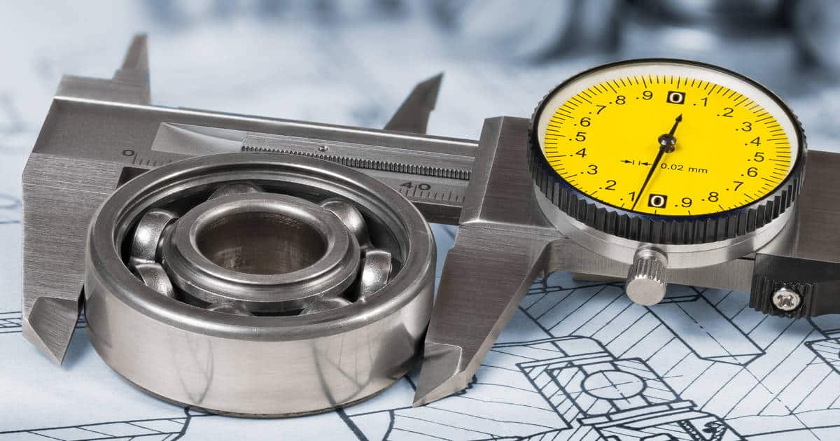
Tolerance Comparison Across All Processes
This is the table that changes most process selection decisions. Before selecting a prototyping process, map your critical tolerance requirements against what each process can reliably deliver.
| Processo | Standard Tolerance | Tight (Process Limit) | Surface Finish As-Built | Post-Processing Max |
| CNC Machining (3-axis) | ±0,05 mm | ±0,01 mm | Ra 1.6 µm | Ra 0.2 µm (polished) |
| CNC Machining (5-axis) | ±0,025 mm | ±0,01 mm | Ra 0.8 µm | Ra 0.1 µm |
| SLA | ±0,1 mm | ±0,05 mm | Ra 0.8–1.6 µm | Ra 0.2 µm (sanded) |
| SLS | ±0.3 mm | ±0.15 mm | Ra 8–16 µm | Ra 3.2 µm (bead blasted) |
| FDM | ±0,5 mm | ±0.2 mm | Ra 25–50 µm | Ra 3.2 µm (sanded) |
| MJF | ±0.3 mm | ±0.2 mm | Ra 8–14 µm | Ra 3.2 µm (bead blasted) |
| DMLS/SLM | ±0.1–0.2 mm | ±0.05 mm (post-machined) | Ra 8–16 µm | Ra 0.4 µm (machined + polished) |
| Vacuum Casting | ±0.2 mm | ±0,1 mm | Ra 1.6–3.2 µm | Ra 0.8 µm |
Practical rule: Any feature requiring assembly fit with clearance less than 0.2 mm demands either CNC machining or SLA. For press fits, bearing seats, or sealing surfaces, CNC machining is the only process that delivers consistent results.
Cost Comparison and Volume Economics
Per-Part Cost by Process and Volume
The following represents typical cost ranges for a medium-complexity part (roughly 100 × 80 × 40 mm, multiple features):
| Processo | 1 Part | 5 Parts | 25 Parts | 100 Parts |
| CNC Machining (Al 6061) | $80–$200 | $55–$120 | $35–$80 | $20–$50 |
| SLA | $30–$80 | $25–$60 | $18–$45 | $12–$30 |
| SLS/MJF | $40–$100 | $30–$75 | $20–$50 | $14–$35 |
| FDM | $10–$30 | $8–$22 | $6–$16 | $4–$10 |
| Impressão 3D em metal | $200–$600 | $180–$500 | $150–$400 | $100–$300 |
| Vacuum Casting | $150–$300 (mold) + $30–$70/part | — | $35–$80 | — |
Vacuum casting’s economic advantage appears at 10–50 units, where the mold cost amortizes and per-unit cost drops well below CNC or SLS equivalents. Below 5 units, CNC or SLA is almost always more economical.
Cost Drivers by Process
CNC machining cost drivers:
- Material — titanium costs 5–8× more per kg than aluminum, and cuts 3–4× slower
- Number of setups — each flip or repositioning adds $30–$80 in setup time
- Tight tolerances — features tighter than ±0.02 mm require slower feeds, additional passes, and more inspection time
- Deep pockets — aspect ratios above 4:1 require specialized tooling and slower programs
- Thin walls below 1 mm — vibration mitigation strategies slow down cutting
Additive process cost drivers:
- Build volume — larger parts cost more; cost scales roughly with bounding box volume
- Support material — complex overhanging geometry in FDM/SLA increases material waste and post-processing time
- Post-processing — smoothing, painting, priming adds $15–$60 per part
- Material class — engineering resins cost 3–5× more than standard resins
Process Selection Framework: Which Process for Your Stage?
Work through this decision matrix by prototype stage and requirement:
Stage 1: Concept Model
Primary goal: Communicate geometry to stakeholders, check proportions. Tolerance requirement: ±1.0 mm or better. Material requirement: None — visual only. Correct process: FDM or SLA. Why not CNC: 5–10× cost premium for no functional benefit at this stage.
Stage 2: Form and Fit Prototype
Primary goal: Verify dimensional fit in assembly, check clearances, validate ergonomics. Tolerance requirement: ±0.2–0.5 mm on non-critical features; ±0.1 mm on mating faces. Material requirement: Stiffness similar to production material; not strength-matched. Correct process: SLA (plastic parts, fine geometry) or CNC machining (metal parts, tight fits). Decision split: If the part is plastic and fits don’t require better than ±0.2 mm, SLA wins on cost. If the part is metal or fits require ±0.1 mm or tighter, CNC machines it.
Stage 3: Functional Prototype
Primary goal: Validate performance under real operating conditions — load, stress, thermal, wear. Tolerance requirement: ±0.05 mm or better on critical dimensions. Material requirement: Must match or closely approximate production material properties. Correct process: CNC machining (metals and engineering plastics) or DMLS (complex metal geometry). Why not SLS/FDM: Anisotropic properties and layer-interface weakness invalidate the test results for load-bearing validation.
Stage 4: Pre-Production Prototype
Primary goal: Validate assembly process, cosmetic appearance, customer review samples. Quantity needed: 10–50 units. Correct process: Vacuum casting (plastic enclosures, consumer products) or CNC machining (metal structural parts). Why not injection molding yet: Tooling cost not justified until design is frozen. Vacuum casting delivers injection molding-like parts at 5–10% of tooling cost.
Stage 5: Pilot Run
Primary goal: Validate production process, train operators, release for regulatory testing or customer approval. Correct process: Production process (injection molding, die casting, stamping) with bridge tooling if production tooling isn’t ready. CNC role: Produces bridge parts and bridge tooling inserts while production tooling is being built.
DFM Rules for Rapid Prototyping: What Changes by Process
Design rules that work for one process fail for another. Here’s what changes:
CNC Machining DFM Rules
| Caraterística | Recommended Design Rule | Reason |
| Internal corner radius | ≥ 1/3 of pocket depth (min 0.5 mm) | End mill diameter limitation |
| Wall thickness (metal) | ≥ 0.75 mm | Vibration and deflection during cutting |
| Wall thickness (plastic) | ≥ 1,0 mm | Clamping force and chatter |
| Hole depth-to-diameter ratio | ≤ 10:1 for standard drilling | Chip evacuation and tool deflection |
| Blind hole threads | Leave 1.5× thread OD of clearance at bottom | Tap clearance |
| Draft angles | Not required (unlike molding) | CNC cuts straight walls reliably |
| Cortes inferiores | Design out if possible; use multi-axis if not | Requires additional setups or 5-axis |
SLA DFM Rules
| Caraterística | Recommended Design Rule | Reason |
| Min. wall thickness | ≥ 0.6 mm vertical; ≥ 1.0 mm horizontal | Cure depth and support load |
| Unsupported horizontal span | ≤ 1.0 mm without support | Resin sag before cure |
| Hole minimum diameter | ≥ 0.5 mm | Resin drain and resolution limit |
| Text/embossed features | ≥ 0.5 mm raised height | Feature resolution at this scale |
| Build orientation | Orient critical surfaces facing up | Downward surfaces rougher |
| Hollow parts | Add drain holes ≥ 3.5 mm | Uncured resin must drain |
SLS/MJF DFM Rules
| Caraterística | Recommended Design Rule | Reason |
| Min. wall thickness | ≥ 0.7–1.0 mm | Powder support and sintering resolution |
| Clearance for moving parts | ≥ 0.5–0.8 mm gap | Powder removal and sintering fusion risk |
| Min. hole diameter | ≥ 1.5 mm | Powder removal from holes |
| Interlocking features | Design for powder removal access | Powder trapped inside can’t be removed |
| Surface finish expectation | Matte, grainy | No inherently smooth surfaces in SLS |
Surface Finish Options After Prototyping
The as-built finish is rarely the final finish. Here’s what’s available by process and what each achieves:
| Finish | Applicable Processes | Result | Impacto nos custos |
| Bead blasting | CNC, SLS, MJF, Metal 3D | Uniform matte, Ra 1.6–3.2 µm | Baixa |
| Polimento | CNC, SLA | Mirror finish, Ra 0.1–0.4 µm | Médio |
| Anodizing (Type II) | CNC aluminum | Protective oxide, color options, 5–25 µm thickness | Médio |
| Anodizing (Type III / hardcoat) | CNC aluminum | Hard 25–100 µm layer, wear resistance | Medium-High |
| Revestimento em pó | CNC, Sheet metal | Durable color finish, 60–90 µm thickness | Médio |
| Niquelagem electrolítica | CNC (metals) | Uniform corrosion protection, 0.001 in thick | Medium-High |
| Painting (primer + color) | CNC, SLA, SLS | Cosmetic finish for customer samples | Médio |
| Tumbling/vibratory | CNC small parts | Deburring, Ra improvement | Baixa |
| Chemical smoothing | SLS/MJF (PA12 only) | Improved surface to Ra 3.2 µm | Baixo-Médio |
Yicen Precision offers 30+ surface finishes applied post-machining or post-printing, including anodizing, powder coating, plating, and polishing.
Rapid Prototyping Lead Times: What Actually Determines Speed
Quoted lead times assume the file is ready to machine. In practice, several factors extend lead time beyond the manufacturing time itself.
| Delay Source | Typical Time Impact | How to Avoid It |
| Missing or incomplete tolerances on drawing | +1–3 days for clarification | Submit complete drawing with STEP file |
| DFM issues requiring design revision | +2–5 days | Request DFM review before committing |
| Material not in stock | +3–7 days for procurement | Confirm material availability at RFQ |
| Secondary process outsourcing (plating, anodizing) | +3–5 days | Choose suppliers with in-house finishing |
| First article inspection and correction | +2–4 days | Build FAI into schedule, not as a surprise |
Em Precisão Yicen, simple CNC parts in standard aluminum ship within 24 hours of order confirmation. Complex 5-axis parts or parts requiring secondary finishing run 3–7 days. Instant online quoting eliminates the quote turnaround delay entirely.
Rapid Prototyping for Regulated Industries
Medical devices, aerospace components, and automotive safety parts have regulatory requirements that change what “prototype” means. In these contexts, a pre-production prototype isn’t just a design validation artifact — it’s a regulatory submission sample or a qualification test article.
Medical Device Prototyping Requirements
Biocompatibility testing under ISO 10993 requires parts made from the exact production-intent material. A PEEK housing prototype made from ABS tells you nothing about biocompatibility. Material selection at the prototyping stage must be production-intent if regulatory testing will be conducted on prototype samples.
Traceability is also required: material certifications, machining records, and inspection data must be retained. A supplier running prototypes without documentation doesn’t qualify as a source for regulatory test samples.
Aerospace Prototyping Requirements
AS9100 suppliers are often required for aerospace prototype parts. First Article Inspection Reports (FAIRs) per AS9102 standard document every dimension on the drawing against actual measured values. Material certifications with traceability to heat lot are standard.
Automotive Prototyping
IATF 16949 governs production, but prototype parts for crash testing, durability validation, or supplier qualification often require dimensional validation packages including CMM reports against the drawing.
Conclusão
Rapid prototyping is not one process. It’s a toolbox of seven distinct processes with different tolerance capabilities, material options, cost structures, and appropriate use cases. Using the wrong tool for the stage you’re in costs you money, time, and in some cases leads you to incorrect design conclusions.
Use FDM and SLA early, fast, and cheap. Use CNC machining when functional performance matters. Use vacuum casting to bridge the gap to injection molding at 10–50 units. Use DMLS only when geometry complexity demands it and metal properties are required. Match the process to the information you need, not to what you used last time.
Precisão Yicen offers CNC machining, 3D printing (FDM, SLA, SLS, MJF), and sheet metal fabrication for rapid prototypes from quantity 1. Upload your file and get an instant quote — parts in as little as 24 hours.
Perguntas mais frequentes
What is the fastest rapid prototyping process for a functional metal part?
CNC machining from standard aluminum stock (6061-T6) is typically the fastest path to a functional metal prototype. Simple parts with no surface finishing requirement can ship in 24 hours from order confirmation. For complex geometry requiring 5-axis machining or tight tolerances below ±0.02 mm, 3–5 days is realistic. Metal 3D printing (DMLS) is slower than CNC for most prototype geometries and requires post-machining of functional surfaces anyway, which adds lead time.
What tolerances can 3D printing actually hold for functional assemblies?
SLA holds ±0.1 mm on features below 50 mm; SLS and MJF hold ±0.3 mm. For assembly fits requiring clearances below 0.2 mm — bearing bores, precision shaft fits, sealing faces — 3D printing cannot reliably deliver compliant parts without post-machining. If your assembly has functional fits below 0.2 mm, machine those features. Either CNC machine the whole part or print the rough geometry and machine the critical interfaces.
When does vacuum casting beat CNC machining for prototype economics?
Vacuum casting beats CNC on per-part cost at quantities above roughly 8–12 parts, once the silicone mold cost ($150–$300 typical) is amortized. A vacuum cast polyurethane part at quantity 25 typically costs $35–$70 per part versus $80–$150 per CNC machined equivalent. The break-even is quantity-dependent and part-complexity-dependent. For large, complex plastic enclosures, vacuum casting wins earlier. For small, simple geometries, CNC remains competitive at lower quantities.
How do I choose between SLS and SLA for a functional plastic prototype?
Choose SLA when surface finish, fine feature detail, or optical properties matter. SLA produces Ra 0.8–1.6 µm as-built and can be sanded smoother — it’s the correct process for appearance models and master patterns for vacuum casting. Choose SLS when internal complexity, moving mechanisms, or interlocking geometry makes supports impractical, or when you need a tougher nylon material that SLA resins can’t match in elongation and fatigue resistance. SLS PA12 has 18% elongation at break; standard SLA resins typically break at 5–15%.
What files do I need to submit for a rapid prototype quote?
A STEP or IGES 3D file is required for an accurate quote on CNC, SLA, SLS, and metal 3D printing. For CNC machining, accompany the STEP file with a 2D drawing that calls out tolerances, surface finish requirements, material specification, and any special notes (thread callouts, flatness, parallelism). Submitting a STEP file alone results in the supplier applying standard tolerances — which may not match your design intent. For additive processes with no tight tolerance requirements, a STEP file alone is usually sufficient.