What Is the 3-2-1 Principle?
The 3-2-1 Principle is a crucial concept used in workpiece positioning within gabarits et montages. It ensures that a part is located and held in the correct orientation and position relative to the machine or tool during manufacturing processes. By limiting the degrees of freedom () of the workpiece, the 3-2-1 method helps achieve consistent, repeatable results in operations like machining, welding, or assembly.
Definition
The 3-2-1 Principle refers to a method of positioning that restricts the six degrees of freedom (three translational and three rotational movements) of a workpiece using a systematic approach. The principle divides the workpiece’s positioning into three steps:
- Three points to restrict the motion along the primary plane.
- Two points to restrict the secondary plane.
- One point to restrict the tertiary plane.
This arrangement results in six points of contact to fully constrain the part, making it immovable during the manufacturing process.
Why It Is Used in Workpiece Positioning
The 3-2-1 Principle is used to ensure accurate, repeatable, and stable positioning of the workpiece. Proper location in the fixture reduces errors caused by part misalignment, ensurinDOFg that operations like drilling, milling, or welding are performed with high precision. It also minimizes the setup time and tooling wear by ensuring that parts are consistently positioned across multiple operations.
Importance in Jigs & Fixtures
In jigs and fixtures, accurate workpiece location is essential for:
- Reducing scrap rates: By ensuring parts are positioned precisely, the chance of errors that lead to defective parts is minimized.
- Optimizing production speed: With correct positioning, setup times are reduced, allowing faster operation and minimizing downtime.
- Ensuring uniformity: Repeatable positioning of parts ensures uniformity across a production batch, which is essential for mass production processes.
Understanding the 3-2-1 Locating Method
The Concept of Six-Point Location
To fully constrain a workpiece, we must limit its movement along all six degrees of freedom (DOF). These six DOFs include:
- Translational movements along the X, Yet Z axes (three directions).
- Rotational movements around the X, Yet Z axes (three rotations).
The 3-2-1 method uses six locator points to restrict these movements, ensuring that the part remains stable and accurately positioned during the machining process.
Three Points to Restrict Primary Plane Motion
Le primary plane is the first surface that defines the part’s position. Typically, this is done using three points. For example, when placing a part on a fixture, three points on a flat surface are used to restrict its movement in the Z-axis (vertical direction) and both the X-axis et Y-axis (horizontal directions).
Tip: To maximize stability, the three points should be as far apart as possible. This helps prevent the workpiece from tipping or shifting during operations.
Two Points for Secondary Plane
Le secondary plane is perpendicular to the primary plane and further restricts movement. Two points are used on this plane to eliminate the remaining degrees of freedom in the X et Y directions, preventing the part from moving horizontally.
One Point for Tertiary Plane
Le tertiary plane is perpendicular to both the primary and secondary planes. One point is used to restrict the final degree of freedom, the rotation around the Z-axis, ensuring that the part does not rotate.
How 6 Degrees of Freedom Are Controlled
By carefully selecting and positioning the locators, the 3-2-1 method effectively controls all six degrees of freedom:
- Three points for the primary plane restrict movement along X, Yet Z axes.
- Two points for the secondary plane limit movement along the X et Y axes.
- One point for the tertiary plane restricts rotational movement about the Z-axis.
How the 3-2-1 Principle Ensures Accuracy
Eliminating Workpiece Movement
By using the 3-2-1 Principle, the workpiece is firmly constrained, preventing it from moving in any direction. This restriction ensures that the cutting tool follows the correct path, resulting in accurate dimensions and precise finishes on each part.
Repeatability in Mass Production
In mass production, it’s vital that each part produced is identical. The 3-2-1 Principle ensures that every part is positioned consistently in the fixture, which guarantees repeatability. Even after multiple setup changes or part replacements, the part remains aligned in the same way every time.
Avoiding Over-Positioning and Redundancy
Over-positioning occurs when unnecessary locators are used, restricting movement in the same direction multiple times. This can cause unnecessary stress on the part or fixture, potentially leading to inaccuracies or damage. The 3-2-1 Principle avoids this by ensuring that each locator serves a unique function, efficiently restricting only the required degrees of freedom.
Types of Locators Used in Jigs & Fixtures
Localisateurs plats
Localisateurs d'appartement are used to position a workpiece based on flat surfaces, often used for larger, simpler parts. These locators provide precise reference points for positioning the workpiece.
Localisateurs cylindriques
Cylindrical locators are used when a workpiece has cylindrical features, such as holes or shafts. These locators are inserted into the part to provide stable, centered support.
Conical Locators
Conical locators have a tapered shape and are ideal for parts that need to be positioned in a way that naturally centers themselves. These locators are especially useful for irregularly shaped parts.
V-Block Locators
V-block locators are shaped to accommodate cylindrical parts. They are commonly used for parts that have round or tubular shapes and need to be positioned securely within the fixture.
Épingles à diamant
Pointes de diamant are small, precisely machined pins used to accurately position parts in fixtures. They are particularly useful for small, intricate workpieces that require precise alignment.
Localisateurs réglables
Localisateurs réglables are used in applications where part dimensions may vary slightly. They can be adjusted to accommodate different sizes, providing flexibility for diverse part designs.
Rest Pads & Support Blocks
Rest pads et support blocks are used to provide additional support to the workpiece, ensuring it remains stable during operations. These components are often used in conjunction with other locators for enhanced stability.
Types of Clamps Used in Jigs & Fixtures
Manual Clamps
Manual clamps are typically operated by hand and are used to hold parts in place. These include:
- Strap Clamps: Provide a simple method to clamp parts securely with adjustable straps.
- Screw Clamps: Use a screw mechanism to apply clamping force.
- Colliers de serrage à genouillère: Leverage a toggle mechanism to generate significant clamping force with minimal effort.
Pinces mécaniques
Mechanical clamps are driven by mechanical systems and are used for applications requiring more force than manual clamps.
- Cam Clamps: Use a cam mechanism to provide strong clamping force with fast action.
- Eccentric Clamps: Utilize an eccentric cam to apply pressure, often used for irregularly shaped parts.
Pneumatic Clamps
Pinces pneumatiques use compressed air to generate clamping force, allowing for faster operation and reduced manual effort.
Hydraulic Clamps
Pinces hydrauliques are powered by hydraulic systems and offer significant clamping force, ideal for high-stress or heavy-duty applications.
Magnetic & Vacuum Clamps
Magnetic and vacuum clamps use magnetic or vacuum forces to secure non-ferrous or delicate workpieces without mechanical pressure.
Quick-Acting Clamps
Quick-acting clamps allow rapid adjustments and setups, reducing downtime during production.
3-2-1 Principle: Complete vs Incomplete Positioning
Complete Positioning
Complete positioning involves fully restricting all six degrees of freedom using six points, ensuring precise placement of the workpiece.
Incomplete Positioning
Incomplete positioning occurs when fewer than six degrees of freedom are restricted. While this can be acceptable for specific operations, it may lead to reduced accuracy if not carefully controlled.
Under-Positioning
Under-positioning happens when some necessary degrees of freedom are left unconstrained. This is not acceptable as it may lead to unstable parts and machining inaccuracies.
Over-Positioning
Over-positioning happens when too many locators are used to restrict movement, which can lead to stress on the workpiece or fixture, causing potential deformation or misalignment.
Common Mistakes When Applying the 3-2-1 Method
Redundant Locating
Using unnecessary locators can lead to inefficiency and errors in part positioning. It’s essential to avoid redundancy to prevent unnecessary stress and potential inaccuracies.
Incorrect Clamp Placement
Incorrectly placing clamps can distort the workpiece or cause uneven clamping forces, leading to machining defects.
Using the Wrong Type of Locator
Choosing the wrong locator type for the workpiece can lead to improper positioning, reducing the overall accuracy of the machining process.
Poor Chip Clearance Considerations
Improper chip clearance can interfere with the locating process, causing the workpiece to shift or become misaligned during machining. It’s essential to ensure that locators and fixtures are designed to handle chip buildup effectively.
Practical Examples of 3-2-1 Principle
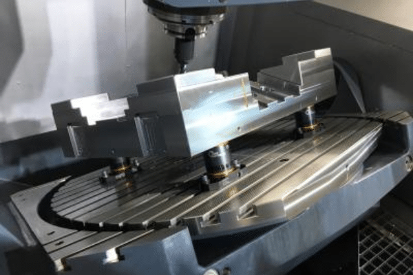
Example with a Rectangular Block
In the case of a rectangular block, three points are used to locate the bottom plane, two points are used for the side plane, and one point secures the top plane to ensure all six degrees of freedom are controlled.
Example with a Cylindrical Component
For cylindrical components, cylindrical locators are used in conjunction with flat locators to secure the part from both the interior and exterior surfaces, ensuring accurate placement.
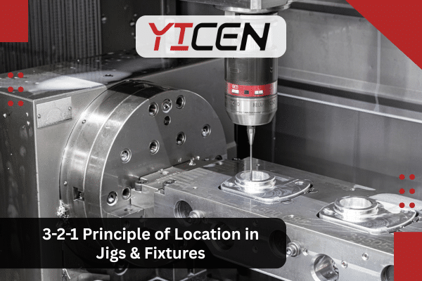
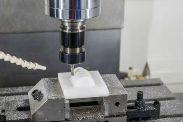
Example in CNC Machining
Machines CNC use the 3-2-1 method to securely locate parts on the machine bed, ensuring high precision during automated cutting or milling operations.
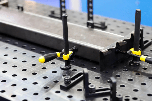
Example in Welding Fixtures
Welding fixtures use the 3-2-1 method to securely position metal components, ensuring that the welds are consistently placed for structural integrity.
Gabarits de soudage et gabarits d'assemblage
Both gabarits de soudage et gabarits d'assemblage play key roles in manufacturing, but they differ in function and usage:
- Welding Jigs: Used during the welding process to hold parts in place and ensure correct alignment, preventing distortion and improving weld quality.
Benefits of Using the 3-2-1 Principle
Increased Accuracy
By precisely restricting the degrees of freedom, the 3-2-1 principle ensures that parts are positioned correctly every time, improving the accuracy of machining operations.
Higher Repeatability
The method ensures that parts are consistently positioned the same way, which is vital for high-volume manufacturing where uniformity is critical.
Reduced Setup Time
The 3-2-1 principle simplifies part setup, reducing the time spent on adjustments and recalibrations.
Lower Manufacturing Errors
By minimizing part movement and misalignment, the 3-2-1 method helps to reduce machining errors, leading to better quality parts and fewer defects.
Making Technical Manufacturing Knowledge Discoverable
Detailed explanations of fundamentals like the 3-2-1 principle are valuable only when engineers, students, and manufacturing decision-makers can actually find them during research. Many technical manufacturing websites struggle not with content quality, but with visibility. Agencies like Wise Rank help industrial and engineering-focused businesses present structured, educational content in a way that aligns with how people search — without compromising technical depth.
Résumé
The 3-2-1 Principle is a fundamental technique used in workpiece positioning within jigs and fixtures. By restricting the six degrees of freedom through three fixed points, two secondary points, and one tertiary point, it ensures accuracy, repeatability, and stability in manufacturing processes. This principle is essential for industries that rely on precision, including automobile, aérospatialeet electronics manufacturing.
FAQ
What is the purpose of the 3-2-1 method?
Le Méthode 3-2-1 is used to accurately locate and constrain a workpiece within a fixture. It ensures that the workpiece is positioned correctly along three primary planes, limiting all six degrees of freedom (translational and rotational) and preventing movement during machining, welding, or assembly.
What industries use the 3-2-1 principle?
Le Principe 3-2-1 is widely used in industries such as Fabrication automobile, aérospatiale, électronique, medical device productionet metalworking, where precision and repeatability are essential for producing high-quality parts.
Why are six points needed for accurate location?
Six points are required to fully restrict all six degrees of freedom of a workpiece, ensuring that it remains stable and immovable during machining. Without restricting all six DOFs, the workpiece could shift, rotate, or vibrate, causing errors in the machining process.
How do clamps and locators work together?
Localisateurs are used to position the workpiece within the fixture, while clamps are used to hold it securely in place. Locators ensure the workpiece is positioned correctly, and clamps prevent any movement or displacement during machining.