A well-prepared CAD file gets quoted faster, machined correctly the first time, and rarely comes back for revision. A poorly prepared one causes the supplier to make assumptions, and those assumptions become first-article failures, re-machining costs, and delayed deliveries.
This guide covers everything you need to submit before an order: file formats, tolerance callouts, geometry requirements, thread specifications, and the final checklist to run before you hit send.
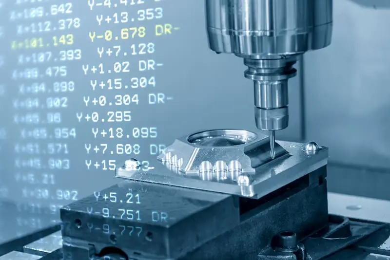
Why CAD File Preparation Directly Affects Your Part Quality and Cost
How you prepare and submit your CAD files determines whether your supplier can quote accurately, program efficiently, and machine your part without ambiguity. Incomplete files create gaps that get filled with guesswork, and guesswork in precision machining is expensive.
The most common file-related problems Yicen Precision sees at the quote stage:
- 3D model submitted without a 2D drawing, so tolerance intent is missing entirely
- Tolerances tighter than necessary on non-functional features, inflating cost
- Sharp internal corners specified in a milled pocket (tool geometry makes these impossible without EDM)
- Thread callouts absent from threaded holes in the 3D model
- Units or scale set incorrectly in the CAD software, producing a model that’s 25.4× the intended size
None of these require advanced engineering knowledge to fix. They just require knowing what to check.
Step 1: Choose the Right File Format
The format you export determines how accurately your geometry transfers to the supplier’s CAM software. Some formats carry full parametric data. Others approximate curves with mesh triangles and lose precision in the transfer.
Preferred formats for 3D models:
- STEP (.step / .stp): The standard for CNC machining. Carries exact geometry, surfaces, and solid body data. Works with virtually all CAM platforms. This is the format to use.
- IGES (.igs / .iges): Widely supported, but sometimes produces open surfaces or non-manifold geometry. Use STEP when possible, IGES as a fallback.
- Parasolid (.x_t / .x_b): Used by some high-end CAM platforms. Excellent fidelity, less universally supported.
Formats to avoid for CNC machining:
- STL (.stl): Approximates surfaces with flat triangles. Resolution loss makes it unsuitable for precision parts. Fine for 3D printing, but not for machining.
- PDF or image-only submissions: These can only define geometry in 2D and carry no dimensional data that a CAM system can use.
2D drawing format: Always submit as a PDF with vector geometry (not a scanned image). The PDF carries your tolerance callouts, surface finish notes, thread specifications, and title block information.
Yicen Precision accepts STEP, IGES, Parasolid, and most standard solid body formats for 3D models, plus PDF for 2D drawings. Upload directly at yicenprecision.com/get-a-quote.
Step 2: Always Include a 2D Drawing
This is the most commonly skipped step and the one that causes the most problems. Your 3D model defines shape. Your 2D drawing defines everything else.
A 2D drawing must include:
- Tolerances on critical dimensions. Bore diameters, shaft fits, positional relationships, and any dimension that affects assembly function.
- General tolerance block. A title block note like “Unless otherwise specified: ±0.1 mm” covers all non-called-out dimensions and removes ambiguity.
- Surface finish callouts. Use Ra values (e.g., Ra 1.6 µm as-machined, Ra 0.8 µm after grinding). Apply these only where surface finish is functionally relevant, not to every face.
- Thread specifications. Call out thread size, pitch, depth, and whether the hole is through or blind. Example: M8×1.25 blind 15 mm. Don’t leave threads to be inferred from the 3D model.
- Material specification. Full alloy designation, not just “aluminum.” Specify “Aluminum 6061-T6” or “Stainless Steel 316L” so there’s no interpretation.
- Post-processing requirements. If the part needs Type II anodize, passivation per ASTM A967, or powder coating, call it out. The finish affects dimensional planning, especially for hard anodize, which adds 0.013 to 0.025 mm per surface.
- GD&T callouts where applicable. Flatness, parallelism, perpendicularity, true position, and runout callouts communicate relationships between features that linear dimensions alone can’t fully define.
If your part is a simple prismatic shape with no critical fits, a 3D file plus a brief written note on material and general finish can be sufficient. For any part with mating surfaces, sealed threads, or regulatory inspection requirements, the 2D drawing is not optional.
Step 3: Define Tolerances Correctly
Tolerances communicate which dimensions are critical and how much variation is acceptable. The goal is to be specific where it matters and relaxed where it doesn’t. Both extremes cost money: over-tolerancing inflates machining and inspection time; under-tolerancing produces parts that don’t assemble or function.
Standard tolerances for CNC machining at Yicen Precision:
| Feature Type | Standard Achievable | Tight (requires specific callout) |
|---|---|---|
| General linear dimensions | ±0.1 mm | ±0.01 mm |
| Precision bores and shafts | ±0.025 mm | ±0.005 mm |
| Thread pitch diameter | Per ISO 2768 | Custom per application |
| Surface finish (as-machined) | Ra 1.6 µm | Ra 0.4 µm (requires finishing pass) |
| Flatness | 0.1 mm over 100 mm | 0.02 mm (requires grinding) |
Rules for specifying tolerances:
Tighten tolerances only on features that affect: mating fits (bore and shaft), sealing surfaces, positional relationships between functional features, and any dimension called out on an assembly drawing.
Leave non-functional faces, cosmetic surfaces, and structural-only features at the general tolerance. One tight callout surrounded by appropriate general tolerances machines faster and costs less than a drawing where everything is tight.
For aerospace and medical device parts, Yicen’s team reviews tolerance stack-ups and confirms achievability before cutting. Our ISO 13485 and IATF 16949 certifications mean we support the full documentation chain these industries require. See our quality assurance page for details.
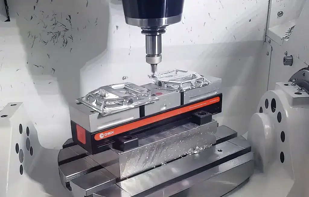
Step 4: Design for Machineability
CAD files that come from solid modeling environments allow features that are impossible or extremely expensive to machine. Reviewing these before submission prevents costly surprises.
Sharp internal corners. Milling cutters are round. They cannot produce a sharp 90-degree internal corner in a pocket. The minimum internal radius equals the tool radius. For a standard 6 mm end mill, the minimum internal radius is 3 mm. Add fillets to all internal pocket corners. If a mating part requires a sharp corner, use a dog-bone relief cut or flag it in the drawing notes.
Thin walls. Metal walls below 0.8 mm deflect during machining and produce chatter, dimensional drift, and surface marks. Walls below 0.5 mm are difficult to machine reliably in most metals. If thin walls are functionally required, note them clearly so the supplier can adjust fixturing and toolpath strategy.
Deep narrow pockets. Pocket depth more than 4× the pocket width causes tool deflection and chip evacuation problems. Above 6:1, cycle time increases significantly and tool life drops. For narrow deep features, wire EDM machining or spark erosion may be a better process choice.
Undercuts. Features that are hidden from vertical tool access require either a T-slot cutter, a lollipop cutter, or additional setups. These are possible but must be flagged so the programmer can plan access. If an undercut is in the design for manufacturing reasons carried over from a different process (such as injection molding), consider whether it’s actually needed in the machined version.
Consistent hole sizes. Non-standard hole diameters require custom tooling or interpolated milling, both of which add cost and sometimes lead time. Where possible, use standard drill sizes (full millimeter or half-millimeter increments, or standard inch fractions). Standard thread sizes similarly avoid specialty tap procurement.
Step 5: Verify Units, Scale, and Orientation
Three simple checks that prevent the most frustrating and avoidable errors.
Units. Confirm your CAD model is set to the unit system you intend to specify on the drawing. Millimeters and inches are both common. Mixed-unit models are a frequent source of quoting errors. Export your STEP file and confirm the bounding box dimensions match your expected part size.
Scale. The model should be at 1:1 scale. CAD software sometimes applies a display scale that looks correct on screen but exports incorrectly. Check the exported STEP file dimensions against your expected envelope.
Orientation. While not strictly required, orienting the model so the most natural machining face is at the bottom reduces back-and-forth with the programming team and speeds up setup. For turned parts, orient the rotational axis along the Z axis.
Step 6: Clean the Model Before Export
A clean 3D model programs faster, machines more accurately, and produces fewer surprises on the shop floor.
Remove before exporting:
- Reference geometry (planes, axes, sketch entities) that aren’t part of the finished part
- Construction features used during modeling that don’t exist on the real part
- Duplicate or overlapping surfaces that create ambiguous solid geometry
- Logos or text embossed on faces unless they are intended to be machined
Check for these geometry issues before submission:
- Non-manifold edges (edges shared by more than two faces, which can confuse CAM software)
- Open shells instead of closed solids
- Zero-thickness faces
- Self-intersecting surfaces
Most CAD packages have a “check geometry” or “diagnose” tool that identifies these issues automatically. Running it takes under a minute and can prevent hours of back-and-forth with your supplier.
The Pre-Submission Checklist
Run through this before uploading any file package.
File package:
3D model exported as STEP or IGES at 1:1 scale with correct units
2D drawing exported as PDF (vector, not scanned image)
Files named clearly: part number, revision, and description
2D drawing content:
Critical dimensions toleranced individually
General tolerance block in title block
Surface finish callouts using Ra values on relevant faces
All threaded holes called out: size, pitch, depth, blind or through
Material specified by full alloy designation
Post-processing requirements noted (anodize type, passivation spec, coating)
GD&T applied where feature relationships need to be controlled
Geometry:
All internal pocket corners have fillets (radius ≥ tool radius, typically ≥ 1 mm)
No walls thinner than 0.8 mm unless flagged in drawing notes
Pocket depth-to-width ratio below 4:1 unless flagged
No sharp undercuts without a machining note
Hole sizes use standard drill dimensions where possible
Verification:
Units confirmed (mm or inches, consistent throughout)
Scale confirmed at 1:1
Bounding box dimensions match expected part size
Geometry check run in CAD software (no open shells, no non-manifold edges)
How Yicen Precision Handles Your Files
When you upload a file package to Yicen, the order flow works like this:
- File receipt and DFM review. Engineers check for machineability issues, tolerance feasibility, material compatibility with the specified finish, and drawing completeness. Any questions come back to you with specific callouts, not a generic “please clarify.”
- Quote generation. Based on your STEP model, drawing, material, tolerance requirements, and surface finish, a full quote is generated with lead time, quantity pricing, and any DFM recommendations.
- CAM programming. Once the order is confirmed, toolpaths are generated and collision-checked before the first cut.
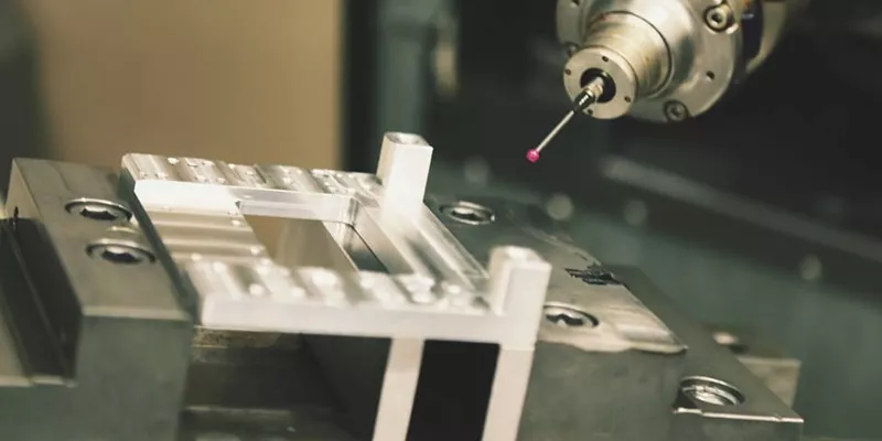
- Production and in-process inspection. CMM probing verifies critical features during and after machining.
- Final inspection and documentation. Dimensional reports, material certs, and any required QA documentation ship with the parts.
Upload your CAD file and get an instant quote. Need a prototype fast? Yicen’s rapid prototyping service delivers qualifying orders in 24 hours.
Frequently Asked Questions
Do I need a 2D drawing if my 3D model has full dimensions?
Yes, for any part with precision tolerances, thread callouts, surface finish requirements, or regulatory inspection needs. The 3D model defines geometry. The 2D drawing communicates tolerance intent, finish requirements, and inspection priorities that aren’t embedded in the solid model.
What tolerance does Yicen apply if I don’t call one out?
Yicen applies ISO 2768-m (medium) as the default general tolerance when no tolerance block is specified. For most features, this means ±0.1 mm on dimensions up to 30 mm. To be safe, include an explicit general tolerance block on your drawing.
What happens if my model has a feature that can’t be machined?
Yicen’s DFM review catches it before cutting starts. You’ll receive specific feedback: which feature, why it’s problematic, and what alternative would work. This happens at the quote stage, before any material is committed.
Can I submit files with inch units?
Yes. Yicen accepts both metric and imperial drawings. Make sure your 3D model and 2D drawing use the same unit system throughout, and confirm the unit system in your drawing title block.
What if I only have a 2D sketch, not a 3D CAD model? Yicen can work from detailed 2D drawings for simple prismatic parts. For parts with complex geometry, a 3D model is required for accurate programming. Contact us at sales@yicenprecision.com if you need guidance on getting started from a 2D sketch.