CNC machines are in every serious manufacturing facility, but most buyers interact with them only through drawings and delivery dates. Understanding what’s actually happening inside the machine — what the controller does, how the axes move, why the setup matters, what G-code is — makes you a better customer. It helps you write better drawings, ask better questions, and understand why certain tolerances cost more than others.
This guide explains how CNC machines work from the ground up: the physical components, the programming sequence, the precision systems that hold tolerance, and how it all comes together to produce a finished part.
The Core Concept: Automated Motion Control
A CNC machine is a computer-controlled machine tool. It reads a program of numerical coordinates and executes a sequence of precise, automated movements that remove material from a workpiece to produce a finished part. Every axis movement, every tool change, every spindle speed, every coolant activation is specified in the program and repeated identically on every part in a production run.
Before CNC, a machinist controlled the machine manually at each step: turning handwheels to position the table, setting spindle speed by hand, reading a dial indicator to confirm position. Skill and attention determined accuracy. Two shifts of work on the same part often produced measurably different results.
CNC replaced all of that manual control with a program. The machine reads numerical coordinates and drives its axes to those positions under closed-loop feedback control. The machinist’s role shifted from operating the cutting tool to programming, setting up, and monitoring the machine.
The result is a system that can hold the same position to within micrometers, run for hours without intervention, and produce part 500 to the same specification as part 1.
The Physical Components of a CNC Machine
Every CNC machine — whether a milling center, a lathe, or a grinding machine — shares the same fundamental mechanical and electronic architecture. The components below are present in some form on all of them.
The Machine Structure
The bed, column, and frame form the rigid structure that holds all other components in alignment. On a vertical machining center, the bed supports the table that carries the workpiece; the column supports the spindle head. Everything that matters about accuracy starts here. A machine with insufficient structural rigidity deflects under cutting forces, causing dimensional drift and poor surface finish.
High-quality machine structures use cast iron or welded steel, sometimes with polymer concrete fill for vibration damping. The geometry of the structure — the squareness of the column to the bed, the straightness of the guideways — is verified during manufacture and periodically recalibrated during the machine’s service life.
The Drive System: How the Axes Move
Each linear axis (X, Y, Z) and rotary axis (A, B, C) is driven by a servo motor connected to a ballscrew or linear motor. When the controller commands a move to a specific position, the servo motor turns, the ballscrew converts that rotation to linear motion, and the carriage or table moves.
The ballscrew converts rotary motion to linear motion with very low backlash. On a quality machine, the positioning error across the full travel of an axis is measured in micrometers.
Closed-loop feedback is what makes this precise. A linear encoder — essentially a very fine ruler attached to the machine’s moving component — continuously reports actual position back to the controller. If the commanded position is 100.000 mm and the encoder reads 100.003 mm, the controller commands a correction move. This feedback loop runs thousands of times per second, continuously correcting any deviation between commanded and actual position.
The Controller
The controller is the machine’s processing unit. It reads the G-code program line by line, interprets each command, and converts it into electrical signals that drive the servo motors. Modern controllers execute real-time position feedback loops, interpolate multi-axis moves (moving X and Y simultaneously to follow a curved path), and manage all the machine’s auxiliary functions: coolant, tool changers, workholding clamps.
The controller also manages limits, alarms, and safety interlocks. If an axis approaches its travel limit, the controller stops the motion before damage occurs.
The Spindle
The spindle holds and rotates the cutting tool (in a mill) or the workpiece (in a lathe). Spindle performance — runout, speed range, power, and thermal stability — directly affects surface finish and achievable tolerance at the tool tip.
A milling spindle holds the tool in a taper (BT, CAT, or HSK) that locates it precisely on the spindle centerline. Runout at the tool tip should be under 5 µm on a precision machine. If the spindle has even 10 µm of runout, every feature the tool cuts will reflect that error.
Spindle speeds on modern machining centers typically range from a few hundred RPM to 15,000–20,000 RPM. High-speed spindles for aluminum can reach 40,000+ RPM. Speed selection depends on the tool diameter and the material being cut; the goal is to achieve the optimal surface speed at the cutting edge.
The Tool Changer
Most CNC machining centers carry multiple cutting tools in an automatic tool changer (ATC) magazine — typically 20 to 60 tools, sometimes more. When the program calls for a tool change, the spindle moves to the change position, the magazine indexes to the correct tool, and the exchange completes in a few seconds. On a complex part, dozens of tool changes may occur in a single program without operator intervention.
Tool identification is managed by the controller’s tool table, which records each tool’s length offset and diameter compensation. When a tool is replaced due to wear, the operator updates these offsets so the new tool cuts to the same dimensions as the previous one.
The Coolant System
Cutting generates heat at the tool-workpiece interface. Without coolant, that heat builds in the tool, causing wear and thermal expansion that changes the part’s dimensions. Coolant manages three things: temperature, lubrication, and chip evacuation.
Standard flood coolant delivers cutting fluid over the cutting zone from nozzles on the machine head. Through-spindle coolant delivers fluid directly through the tool’s internal channels to the cutting edge — essential for drilling deep holes and machining difficult materials like titanium. High-pressure through-spindle coolant (70–100 bar) also blasts chips clear of the cutting zone, preventing re-cutting and tool damage.
The Programming System: From CAD to G-Code
The program that runs a CNC machine starts as geometry in a CAD file and ends as G-code. Understanding the transformation helps buyers and engineers prepare better files and specifications.
CAD: The Geometry Model
The process starts with a 3D solid model of the part. The model defines exact geometry: every surface, edge, hole, and thread. A 2D drawing paired with the model communicates what the CAD model can’t: tolerance callouts on critical features, surface finish requirements, thread specifications, material, and post-processing instructions.
The quality of the CAD file directly affects programming speed and accuracy. Clean geometry with no open surfaces or duplicate entities programs quickly and produces reliable toolpaths. Poorly constructed models require manual repair before programming can begin.
CAM: Generating the Toolpaths
A programmer loads the 3D model into CAM software and generates toolpaths. For each operation — roughing a pocket, finishing a bore, drilling a pattern of holes — the programmer selects the tool, defines the cutting strategy, and sets feeds and speeds. The CAM software calculates the exact path the tool must follow to produce the geometry, accounting for the tool’s diameter and the material being cut.
Before generating G-code, the programmer runs a simulation that shows the tool moving through the material in a virtual machine. The simulation checks for collisions between the tool, holder, and any fixture components. Catching a collision in simulation costs nothing. Catching it on the machine costs the workpiece, the tool, and potentially the spindle.
G-Code: The Machine’s Language
CAM software exports the toolpaths as G-code: a sequence of alphanumeric commands that the controller reads line by line. A few foundational codes:
- G00 – Rapid positioning (move to coordinate at maximum speed, no cutting)
- G01 – Linear interpolation (feed move: cut in a straight line at programmed feed rate)
- G02 / G03 – Circular interpolation (cut a circular arc, clockwise or counterclockwise)
- G41 / G42 – Tool radius compensation (offset the tool path by the tool’s radius, left or right)
- M03 / M04 – Spindle on, clockwise or counterclockwise
- M06 – Tool change
- M08 / M09 – Coolant on / off
A typical G-code program for a production part runs hundreds or thousands of lines. Modern controllers also support high-level parametric programming for features like bolt hole circles, thread milling, and probing cycles, which generate the underlying G-code automatically from simple inputs.
Setup: The Step That Determines Accuracy
Programming gets the tool to the right path. Setup determines whether the part is in the right place to benefit from it.
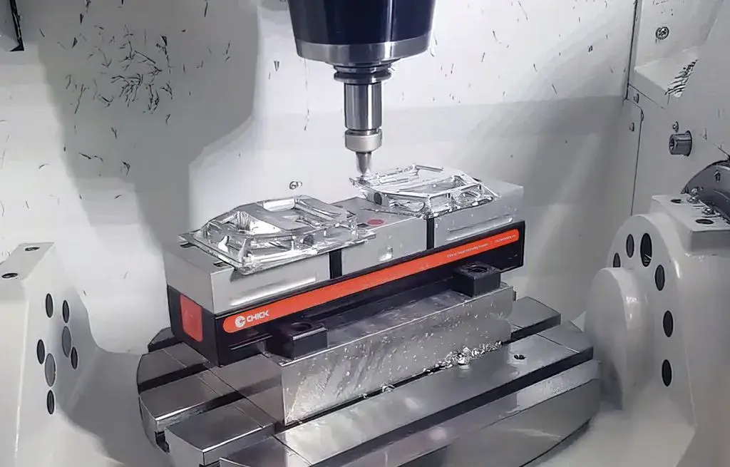
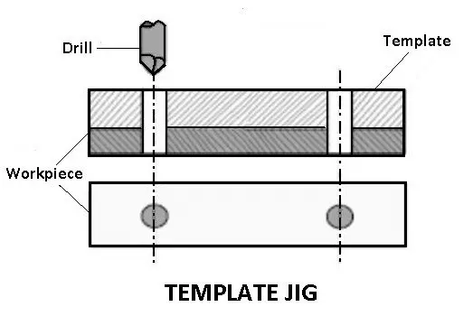
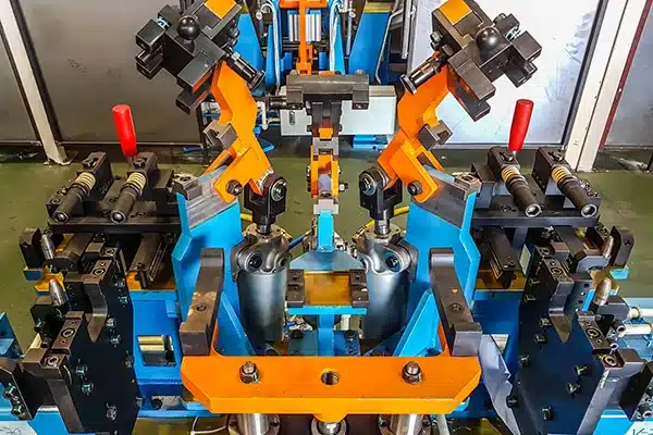
Porta-peças
The workpiece must be located accurately — positioned against a known datum — and clamped rigidly enough to resist cutting forces without moving. Every CNC machining method has characteristic workholding: vises and fixture plates for milling, chucks and collets for turning.
The datum scheme matters as much as the clamping. Every time a part is unclamped and re-fixtured in a new position, the relationship between the new datum and the previous one carries a positioning error — typically 0.01 to 0.05 mm depending on the fixturing method. On a part where hole positions across two setups must agree to ±0.01 mm, this datum error becomes the dominant source of variation.
Minimizing setups is one of the most effective ways to improve accuracy and reduce cost simultaneously. A 5-axis machine that can machine five faces of a part in one clamping avoids four separate datum transfers. A mill-turn machine eliminates the turning-to-milling transfer. Yicen Precision’s engineering team evaluates setup strategy during DFM review on every order.
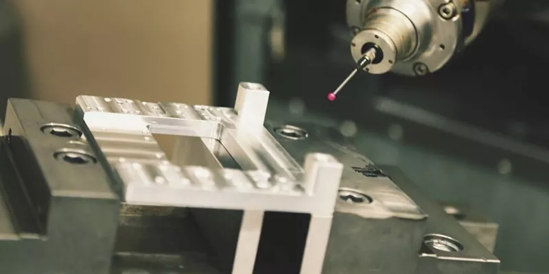
Work Coordinate Setting
After the part is clamped, the operator or probing system establishes the work coordinate system (WCS): the reference point from which all axis moves in the program are measured. A touch probe locates the corner or center of the part and sets the zero point. The program then executes relative to that origin.
If the work coordinate is set incorrectly — even by 0.1 mm — every feature in the program will be offset by that amount. Probing systems that automatically measure and set the WCS eliminate this manual error source.
How Precision Is Maintained During Cutting
Positioning accurately to a coordinate is necessary but not sufficient. Several factors affect whether the finished dimension matches the programmed dimension.
Tool Wear Compensation
Cutting tools wear progressively. As a milling cutter wears, its effective diameter decreases; as a turning insert wears, its cutting-edge geometry changes. Both effects cause the finished dimension to drift over time. Modern CNC machines compensate through tool offset values: the programmer inputs the tool’s measured diameter and length, and the controller adjusts all axis moves accordingly. When a worn tool is replaced, the new tool is measured and the offset is updated.
For precision work, in-process probing measures the actual dimension of a machined feature and adjusts the tool offset automatically to compensate for any drift before cutting the next part.
Thermal Effects
Cutting generates heat. Heat causes the machine structure, spindle, and workpiece to expand. A spindle that grows 0.01 mm over a shift will cut bores 0.02 mm larger in diameter (both sides affected) unless compensated.
Quality CNC machines include thermal compensation models that predict and correct for expansion based on temperature sensor readings throughout the machine. Yicen’s facility maintains controlled ambient temperature to minimize thermal variation across production shifts.
Cutting Parameter Selection
Feed rate, depth of cut, and spindle speed affect the cutting forces the machine experiences during production. Cutting too aggressively deflects the tool away from the programmed path, causing dimensional errors and poor surface finish. Cutting too conservatively increases cycle time and can cause rubbing rather than cutting, generating heat without productive material removal.
Experienced programmers select parameters that balance cycle time against part quality for the specific material, tool, and geometry combination.
From Machine to Finished Part: Inspection and Post-Processing
Machining is followed by inspection and, usually, surface treatment before shipment.
Métodos de inspeção
Yicen Precision uses coordinate measuring machines (CMM) to verify critical dimensions against the drawing. A CMM uses a precision probe to touch the part’s surfaces at specified locations and computes the actual geometry relative to a reference frame. CMM data is exported as a dimensional report that documents compliance with every toleranced dimension.
For first articles and production qualification, Full Article Inspection (FAI) reports provide complete dimensional records. Statistical process control (SPC) data is available for production customers who need ongoing capability evidence.
Surface Treatment
Most machined parts require surface treatment before they’re suitable for service. Treatment options depend on the base material:
- Alumínio: Type II anodize (decorative, corrosion-resistant), Type III hardcoat anodize (wear-resistant, up to 60–70 HRC surface hardness), alodine/chromate conversion, revestimento em pó
- Aço inoxidável: Passivation (removes free iron, restores native oxide layer), electropolishing, bead blasting
- Aço: Zinc plating, electroless nickel, black oxide, hard chrome
- Titanium: Anodizing (produces colored oxide, no dye), passivation, bead blasting
All surface treatments at Yicen are applied in-house. See the full catálogo de acabamentos de superfície for options across all materials. Dimensional planning for surface treatment is important: hard anodize adds 0.013 to 0.025 mm per surface, so bore dimensions must account for the coating before machining.
Precision Summary: What CNC Machines Can Hold
| Feature Type | Standard Production | Tight (with controlled setup) |
|---|---|---|
| General linear dimensions | ±0,1 mm | ±0,01 mm |
| Precision bores (milling) | ±0,025 mm | ±0,005 mm |
| Precision diameters (turning) | ±0,025 mm | ±0,005 mm |
| Surface finish (as-machined) | Ra 1,6 µm | Ra 0,4 µm |
| Surface finish (grinding) | Ra 0,4 µm | Ra 0,2 µm |
| Flatness (over 100 mm) | 0,05 mm | 0.01 mm (with grinding) |
These figures reflect Yicen Precision’s standard production capability. Tighter tolerances require specific fixturing, in-process probing, and controlled environments, and they add to cost and inspection time.
Yicen Precision’s CNC Operation
Yicen Precision operates 300+ CNC machines at our Shenzhen, Bao’an District facility, covering 3-axis through 5-axis milling, CNC turning, turn-mill, EDM de fio, Perfuração CNC, retificação de precisãoe surface grinding.
All orders receive DFM review, in-process inspection, and CMM dimensional reporting. Material certificates, FAI reports, and traceability documentation are standard for aeroespacial, dispositivo médicoe automóvel customers.
Certifications: ISO 9001:2015, ISO 13485, IATF 16949, ISO 14001. Quality assurance details.
Materials: 50+ options. Full materials library.
Lead time: 1–5 days for prototypes, 24-hour option for qualifying orders. Rapid prototyping service.
Carregue o seu ficheiro CAD para obter um orçamento imediato. Contact: sales@yicenprecision.com | +86 0755 2705 2682. Response within 12 hours.
Perguntas mais frequentes
What is G-code and do I need to understand it to order parts?
G-code is the programming language CNC machines execute. It’s generated automatically by CAM software from your 3D model. Buyers don’t write or read G-code; Yicen’s programmers generate and validate it. Understanding what it does — coordinate moves, speed commands, tool changes — helps you understand why certain geometries are more complex to program than others.
Why do tighter tolerances cost more?
Tight tolerances require slower feed rates (more machine time), additional finishing passes, in-process inspection to verify the dimension during cutting, and CMM inspection at the end. Each of these adds cost. Applying tight tolerances only to features that need them — mating bores, functional surfaces, positioned holes — keeps those costs where they create value.
What causes a part to be out of tolerance?
Common causes: tool wear that hasn’t been compensated, thermal expansion during a long production run, workholding that isn’t rigid enough and allows the part to deflect during cutting, programming errors in tool offset values, and chip accumulation that prevents proper workpiece seating in the fixture. In-process probing catches most of these before they produce scrap.
How many parts can a CNC machine run unattended?
It depends on part complexity, cycle time, and how the machine is loaded. A lathe with bar feed and a part catcher can run a full bar of material unattended — potentially 50 to 200 small parts. A machining center with a pallet changer can run multiple fixtures unattended through a lights-out shift. Complex five-axis parts with manual loading typically require operator presence between cycles.
How does a 5-axis machine differ from a 3-axis machine in terms of precision?
Both machine types can hold similar tolerances on qualified features. The 5-axis machine’s advantage is accuracy across multiple faces: because all features are machined from one datum in one setup, the positional relationships between features on different faces are held to the machine’s inherent positioning accuracy rather than accumulated across multiple fixture transfers. This is particularly important for aerospace and medical parts where feature-to-feature relationships are critical.