The choice between milling and turning isn’t a preference. It follows directly from your part’s geometry. Get the match right and you get better tolerances, fewer setups, shorter lead time, and lower cost. Get it wrong and you add fixturing complexity, accumulate datum errors between setups, and pay for machine time you didn’t need.
This guide explains how each process works, where each one is dominant, where they overlap, and exactly how to decide which one your part needs.
The Core Difference: What Moves and What Doesn’t
CNC milling holds the workpiece stationary and moves a rotating cutting tool through the material along programmed axes. CNC turning holds the cutting tool stationary and rotates the workpiece in a chuck, shaping it by bringing the tool against the spinning material.
That mechanical difference determines almost everything else about which parts belong on which machine.
Milling excels when the feature set is prismatic: flat faces, pockets, slots, bosses, holes positioned across multiple planes, and 3D contoured surfaces. The tool can approach the material from any accessible angle, enabling features on multiple faces in a single setup.
Turning excels when the part is rotationally symmetric: shafts, bushings, sleeves, fittings, nozzles, and any component where the primary geometric requirement is a consistent diameter, a concentric bore, or a thread on a round body. The rotating workpiece ensures that the cut follows a perfect circle on every revolution, which is why lathes produce the best concentricity and roundness of any machining method.
CNC Milling: How It Works and When to Use It
How milling works
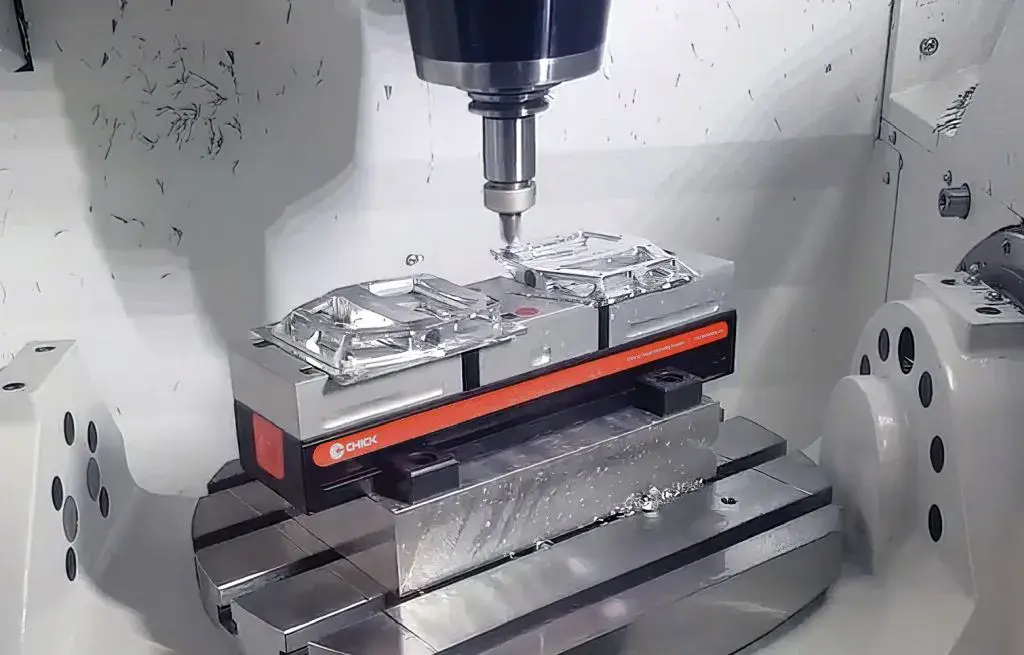
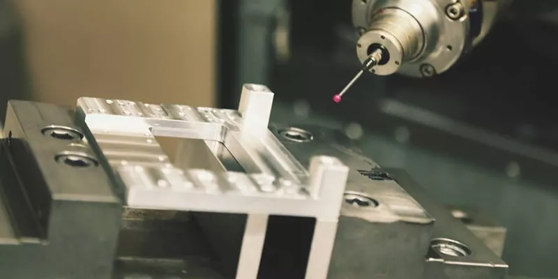
A spindle holds the cutting tool and drives it at high speed. The machine moves the tool (or the table carrying the workpiece) through the material in programmed paths, removing chips with each pass. On a 3-axis machine, movement is along X, Y, and Z. On a 5-axis machine, the tool can also tilt and rotate, enabling it to reach compound angles without repositioning the part.
Workholding in milling uses vises, modular fixture plates, soft jaws, and vacuum tables. The part is located against datums (reference surfaces) and clamped. Every time the part is unclamped and re-fixtured, a new datum error is introduced. Good programming consolidates as many features as possible into a single setup to minimize this.
What milling produces
- Flat faces and steps
- Pockets and slots at any depth the tool can reach
- Drilled, bored, and tapped holes
- Complex 3D contours (with 4- or 5-axis capability)
- Accurate positional relationships across multiple faces
When to specify milling
Milling is the right choice when:
- The dominant features are flat, pocketed, or positioned across multiple planes
- True position of holes or bosses relative to other features is the critical tolerance
- Flatness, parallelism, or perpendicularity is more important than concentricity
- The part has no axis of rotational symmetry (housings, brackets, plates, manifolds)
- Complex surface geometry requires multi-axis tool access
Yicen Precision's CNC milling service runs 3-axis through 5-axis capability. For parts where multiple faces need simultaneous access, Usinage CNC à 5 axes eliminates intermediate setups entirely.
CNC Turning: How It Works and When to Use It
How turning works
The workpiece is held in a chuck or collet and spun at programmed speed. A cutting insert on a tool holder is brought into contact with the rotating material, removing a continuous ribbon of chip. Because the workpiece rotates, every cut naturally follows a circular path, making turning the most efficient way to produce cylindrical geometry.
Modern CNC turning centers add live tooling (driven milling spindles mounted on the turret) and Y-axis capability, allowing cross-holes, flats, and keyways to be added to a turned part without leaving the machine. This combination, often called mill-turn or turn-mill, covers a large proportion of real-world parts that have both cylindrical bodies and prismatic features.
What turning produces
- External diameters (OD features) with tight roundness and concentricity
- Internal bores (ID features) with excellent diameter control
- Threads, external and internal, at standard or custom pitches
- Tapers and radii on rotationally symmetric bodies
- Parting and grooving for snap rings, seals, and reduced sections
When to specify turning
Turning is the right choice when:
- The part is primarily cylindrical: shafts, bushings, sleeves, nozzles, collets
- Concentricity between OD and ID features is the critical tolerance requirement
- Runout and roundness must be controlled tightly (bearings, seals, precision spindles)
- The part will be produced from bar stock, enabling efficient bar-feed automation
- A high-volume round part needs consistent cycle times at production scale
Yicen Precision's Service de tournage CNC handles materials from aluminum to titanium and stainless, with live tooling capability for combined features.
Mill-Turn: When One Machine Does Both
Many real parts aren’t purely milled or purely turned. A shaft needs turned diameters and a milled keyway. A hydraulic fitting needs a turned body and cross-drilled ports. A servo motor housing needs a bored bore and milled mounting faces.
Mill-turn machines combine a lathe spindle with milling capability in one platform. The part is chucked once, all turning operations are completed, then the spindle indexes and the live tooling mills any prismatic features. The part comes off the machine complete, without being transferred to a second setup.
The dimensional advantage is significant. Because every feature is machined from the same datum in one chucking, the positional relationship between the bore axis and the mounting face, or between the thread and the cross-hole, is held to the machine’s inherent positioning accuracy, not accumulated across two separate setups.
When to use mill-turn:
- Round parts with cross-holes, flats, keyways, or small pockets
- Parts where the positional relationship between turned and milled features is critical
- Medium-to-high volume production where reducing setups directly reduces cost
- Any part where re-chucking introduces concentricity risk on precision bores
Side-by-Side Comparison
| Facteur | Fraisage CNC | Tournage CNC | Mill-Turn |
|---|---|---|---|
| Mouvement primaire | Rotating tool, stationary workpiece | Rotating workpiece, stationary tool | Both, in sequence |
| Géométrie idéale | Prismatic: flats, pockets, slots, multi-face | Cylindrical: shafts, bores, threads | Round bodies with prismatic features |
| Primary tolerance driver | True position, flatness, perpendicularity | Concentricité, rondeur, faux-rond | Both, from one datum |
| Maintien de la main d'œuvre | Vise, fixture plate, soft jaws | Chuck, collet, soft jaws, bar feed | Chuck with live tooling |
| Number of setups | 1–2 for most prismatic parts | 1 for most round parts | 1 for combined geometry |
| Surface finish capability | Ra 0.4 µm with fine finishing | Ra 0.4 µm with correct insert/feed | Ra 0.4 µm on both feature types |
| Volume scaling | Efficient for small-to-mid batches | Excellent for high volume with bar feed | Efficient for complex parts at any volume |
| Typical applications | Housings, brackets, manifolds, plates | Shafts, bushings, fittings, fasteners | Motor shafts, hydraulic bodies, valve bodies |
The Decision Framework: Four Questions That Determine the Process
Question 1: What is the dominant geometry? If most features are diameters, bores, and threads on a round body: start with turning. If most features are faces, pockets, and holes on a non-round body: start with milling. If both feature sets are present and their relationship is critical: consider mill-turn.
Question 2: What is the primary tolerance driver? Concentricity, roundness, and runout: turning is the natural process. True position, flatness, and perpendicularity across multiple faces: milling is the natural process. Both in the same part: mill-turn, or a very well planned two-machine route with controlled datum transfer.
Question 3: How does the part arrive at the machine? Bar stock is most efficiently processed on a lathe with bar feed. Plate or billet is most efficiently clamped in a milling vise or fixture. The stock form often confirms the process choice before any other analysis.
Question 4: What volume are you targeting? High-volume round parts scale efficiently on turning centers with bar feed automation. Small-to-medium batches of prismatic parts suit milling. For complex parts at any volume, mill-turn reduces setup count and improves accuracy simultaneously.
Cost Drivers for Each Process
Understanding what drives cost in each process helps you design and specify more economically.
In milling, the main cost levers are:
- Number of setups: each re-fixture adds setup time and a potential datum error
- Pocket depth-to-width ratio: deeper narrow pockets require slower feeds and smaller tools
- Internal corner radii: sharp corners require EDM or very small tools; fillets sized to the tool reduce time significantly
- Tolerance concentration: tight tolerances on many features increase CMM inspection time
- Unnecessary surface finish callouts: specifying fine finish on non-functional faces adds finishing passes without value
In turning, the main cost levers are:
- Stock diameter relative to finished part diameter: oversized stock means more material removed, longer cycle time
- Thread complexity: non-standard pitches or threads requiring custom tooling add cost
- Bore depth-to-diameter ratio: deep bores in small diameters require boring bars and careful chip evacuation
- Live tooling features on a standard lathe: if milled features are complex, a mill-turn or two-machine route may be more efficient than extensive live tooling work
Yicen Precision provides DFM (Design for Manufacturability) feedback at the quote stage on every order for both milling and turning, flagging features that can be simplified without affecting function. Get an instant quote and DFM review.
Materials, Tolerances, and Finishes
Both milling and turning work across the same broad material set. Process choice doesn’t limit material selection; geometry does.
Common materials at Yicen: Aluminum 6061-T6, 7075-T6; stainless steel 303, 304, 316L, 17-4 PH; carbon steel 1018, 4140; titanium Ti-6Al-4V; brass, copper, bronze; engineering plastics including PEEK, Delrin, nylon, and PTFE. Full materials library here.
Standard tolerances at Yicen Precision:
- General dimensions: ±0.1 mm
- Precision bores and shafts (milling and turning): ±0.005 mm with controlled setup
- Thread pitch diameter: per ISO standard or custom callout
- Surface finish (as-machined): Ra 1.6 µm standard
- Surface finish (fine finishing pass): Ra 0.4 µm
Surface treatment options: Type II and Type III anodize, passivation, revêtement en poudre, zinc plating, bead blasting, electropolishing. All applied in-house. Full catalogue d'état de surface.
Inspection et documentation sur la qualité
Both milled and turned parts at Yicen receive dimensional inspection before shipment. CMM inspection confirms critical features against the drawing. For first articles, FAI reports with full dimensional data are provided.
Yicen holds ISO 9001:2015, ISO 13485, and IATF 16949 certifications, supporting full quality documentation for aérospatiale, dispositif médicalet automobile customers. Material certificates and RoHS declarations are available on request. Quality assurance details here.
Questions fréquemment posées
Can the same part use both milling and turning?
Yes, in two ways. A mill-turn machine performs both operations in one setup. Alternatively, a part can be turned on a lathe and then fixtured on a milling machine for a second operation. Mill-turn is preferred when the dimensional relationship between turned and milled features is critical, because both operations share the same datum.
Which process is faster?
It depends on the geometry. Turning is highly efficient for round parts, especially with bar feed — cycle times can be under a minute for small bushings. Milling speed depends on the number and depth of features. High-speed milling of aluminum can be very fast; deep pocketing in steel is slower. Neither process is universally faster; the right process for the geometry is the faster one.
What’s the tightest tolerance achievable on a turned bore?
Yicen holds ±0.005 mm on turned precision bores with controlled setup and appropriate tooling. For the tightest bore fits (H7/h6 class and tighter), meulage de précision after turning is the most reliable path to consistent compliance.
Does Yicen offer both milling and turning on the same order?
Yes. Most production parts at Yicen involve multiple processes. Milling, turning, drilling, EDM, grinding, and surface treatment are coordinated in-house without third-party handoffs.
How do I specify which process to use on my drawing?
You don’t need to specify the process. Your drawing defines the geometry and tolerances; Yicen’s engineering team selects the most appropriate process during DFM review. If you have a preference or a reason to specify (e.g., the part must be produced from bar stock), note it in the drawing notes or order instructions.