At Yicen Precision, our Direct Metal Laser Sintering (DMLS) technology delivers fully dense, high-strength metal components with intricate internal geometries. We offer a wide range of materials, precise tolerances, and flexible build sizes, ensuring optimal performance for prototypes and production parts. With certifications like ISO 9001:2015 and ITAR compliance, we guarantee reliable, high-quality solutions for your most complex manufacturing needs.
Yicenprecision Instant Quoting Engine is covered by U.S. Pat. Nos. 11,086,292, 11,347,201, 11,693,388, 11,698,623, 12,099,341, and 12,189,361. Other patents pending.
What Is Direct Metal Laser Sintering (DMLS)?
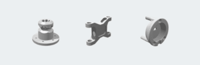
Direct Metal Laser Sintering (DMLS) is an advanced laser-based additive manufacturing process used to produce high-performance metal parts. Through the use of fine metal powders, DMLS fuses layers together, creating strong and precise components with complex geometries. This process allows for efficient production of metal parts with minimal material waste.
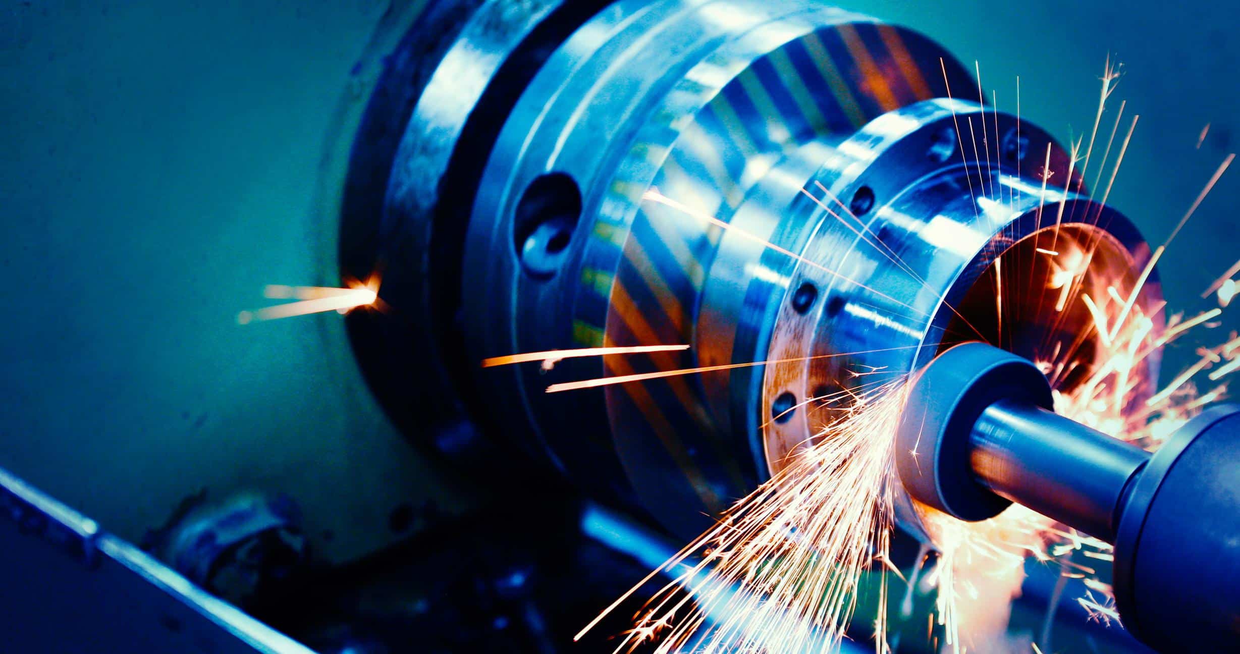
Laser-Based Additive Manufacturing
DMLS uses high-powered lasers to sinter metal powder into solid parts.
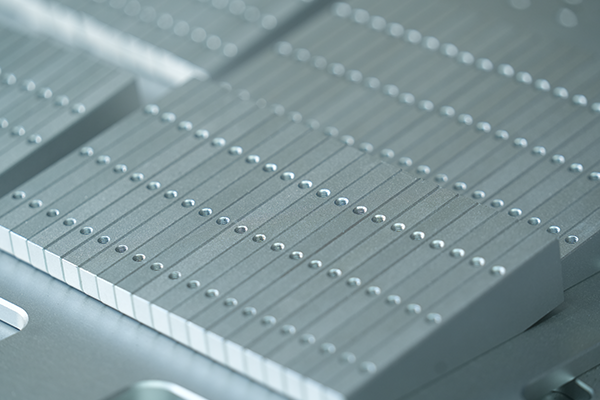
Layer-by-Layer Construction
Metal powder is fused one layer at a time, enabling the creation of intricate designs.
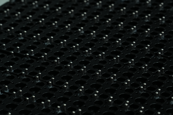
Near-Fully Dense Metal Components
DMLS produces parts with high strength and density, suitable for demanding applications.
DMLS Tolerances, Resolution & Build Sizes
For precise manufacturing, Direct Metal Laser Sintering (DMLS) offers high accuracy in dimensional tolerances, layer height, and feature size. Whether you need detailed components or larger parts, we ensure top-quality production with the highest standards of precision and durability.
Specification
Details
Typical Dimensional Tolerances
±0.001 inches (±0.025 mm), depending on part complexity and geometry
Layer Height Options
20 – 100 microns, offering flexibility in part resolution and surface finish
Minimum Feature Size
0.2 mm, ensuring fine details for intricate geometries
Wall Thickness Guidelines
Minimum of 0.5 mm for optimal strength and durability
Flatness & Warpage Considerations
Controlled during post-processing to ensure flat, dimensionally stable parts
Materials for Direct Metal Laser Sintering (DMLS) Service
At Yicen Precision, we offer a wide range of high-quality materials for Direct Metal Laser Sintering (DMLS), ensuring the production of strong, durable, and precise metal components for your projects. Our selection of materials is ideal for industries requiring high-performance parts, such as aerospace, automotive, and medical applications.
Material
Description
Applications
Stainless Steel 17-4 PH
Excellent corrosion resistance and high strength in harsh environments.
Aerospace, Military, Industrial Applications
Stainless Steel 316L
Highly resistant to corrosion, making it ideal for marine environments.
Marine, Medical, Chemical Processing
Aluminum AlSi10Mg
Lightweight with good strength, widely used for functional parts.
Automotive, Aerospace, Industrial Components
Titanium Ti6Al4V
Known for its strength and lightweight properties, excellent for aerospace.
Aerospace, Medical, High-Performance Components
Inconel 718
High resistance to heat and corrosion, suitable for extreme environments.
Aerospace, Military, Energy Generation
Design Guidelines for Direct Metal Laser Sintering (DMLS)
For optimal performance and cost-efficiency, understanding and following design guidelines for Direct Metal Laser Sintering (DMLS) is essential. These guidelines ensure your parts are fabricated with the highest strength, accuracy, and cost-effectiveness, meeting both functional and aesthetic requirements.
Design Parameter
Specification
Minimum Wall Thickness
Metals: 0.5 mm (for functional strength and stability)
Plastics: 1.0 mm (required to prevent warping or structural issues)
Feature Size Limits
Smallest features: 0.2 mm for precise detail and geometry.
Larger features require careful balancing to ensure strength and structural integrity.
Support Structure Considerations
Use minimal support structures to reduce post-processing efforts. Ensure structures are easy to remove without damaging the part.
Supports must be designed to avoid internal stresses and support complex geometries.
Orientation for Strength & Accuracy
Parts should be oriented to optimize mechanical properties in critical load-bearing areas.
Maximize strength by aligning with the build direction.
Design Tips to Reduce Cost
Minimize the need for support structures by designing parts with self-supporting geometries.
Keep geometries simple and avoid overly intricate features unless required for functionality.
Hole Sizes & Depth
Avoid excessively small holes (min. 0.2 mm) and ensure sufficient depth for chip removal.
Internal Geometries
Complex internal channels, like cooling channels, can be created but should have a minimum width of 0.5 mm.
Part Consolidation
Consider consolidating multiple components into a single part to reduce material waste and cost.
Surface Finishing & As-Printed Quality for DMLS Parts
At Yicen Precision, we provide a range of surface finishing options to enhance the functionality, durability, and appearance of your Direct Metal Laser Sintering (DMLS) parts. Whether you need the raw, as-printed finish or a polished cosmetic appearance, we ensure each part meets the highest standards of quality and performance.
As-Printed (Laser Sintered)
The default finish directly from the DMLS process, ideal for functional parts with a slightly rough surface texture. This finish provides the strongest part integrity without additional treatments.
Bead Blasted (Standard)
This process creates a smooth, matte finish using abrasive media, perfect for applications that require an improved aesthetic with uniform surface texture. It enhances the part’s surface while retaining strength.
Machined Surfaces
For parts that require extra precision, our machining process can further refine surface details, providing a high degree of smoothness and dimensional accuracy for tight tolerance applications.
Polished / Cosmetic Finishing
Achieve a glossy, mirror-like finish suitable for decorative or high-visibility parts. Polishing removes any surface imperfections, providing a smooth, aesthetically pleasing result ideal for consumer-facing applications.
Quality Assurance & Inspection Capabilities
At Yicen Precision, we ensure that each part meets the highest standards of quality through rigorous inspection and testing. Our commitment to precision is backed by our compliance with ISO 9001:2015, AS9100D, and ISO 13485 standards, ensuring reliability and consistency at every stage of production.
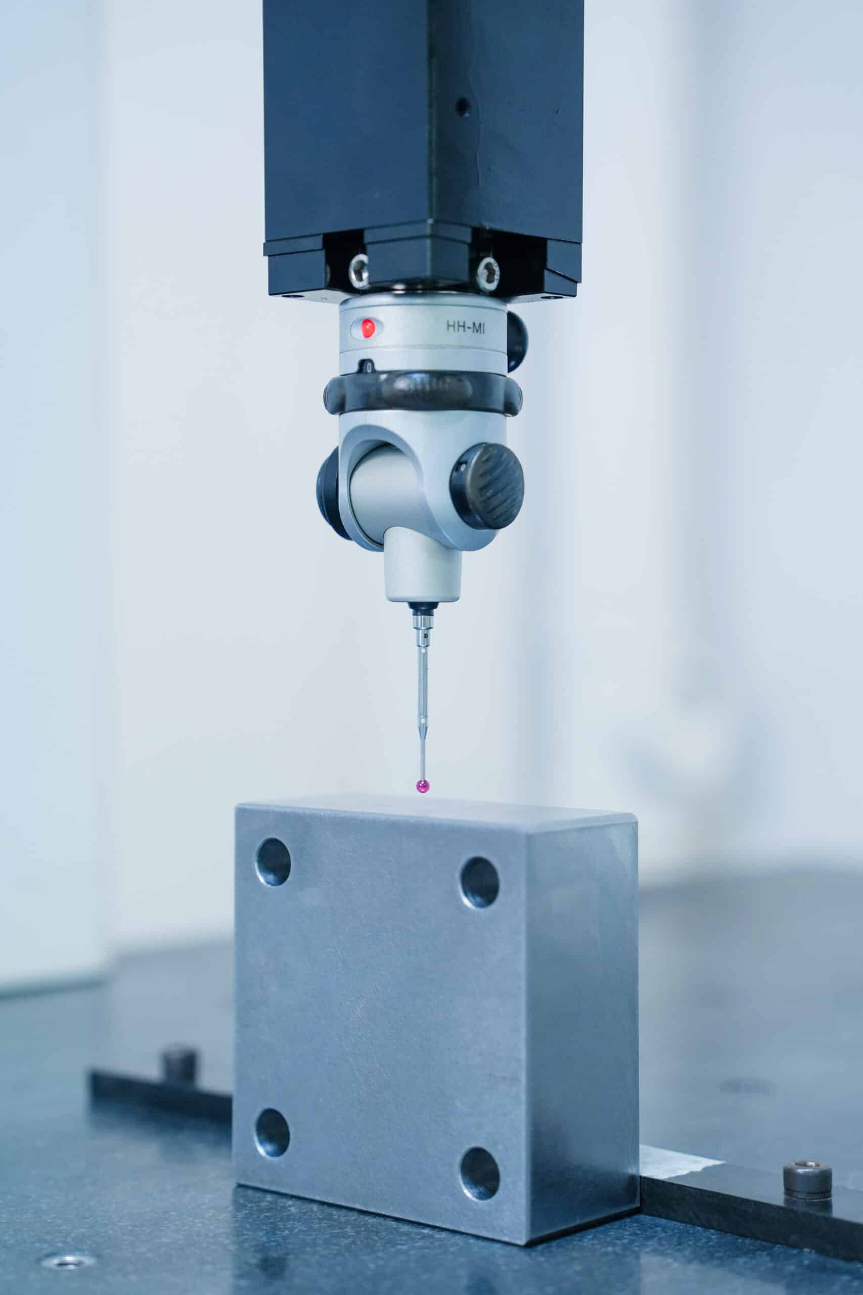
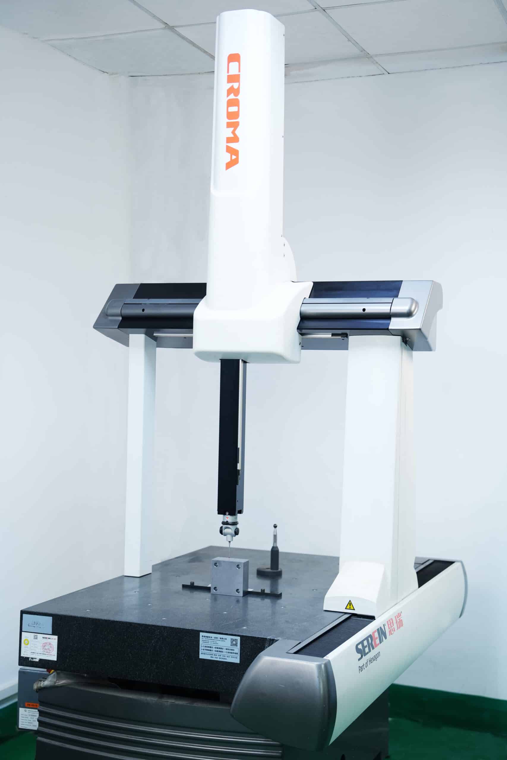
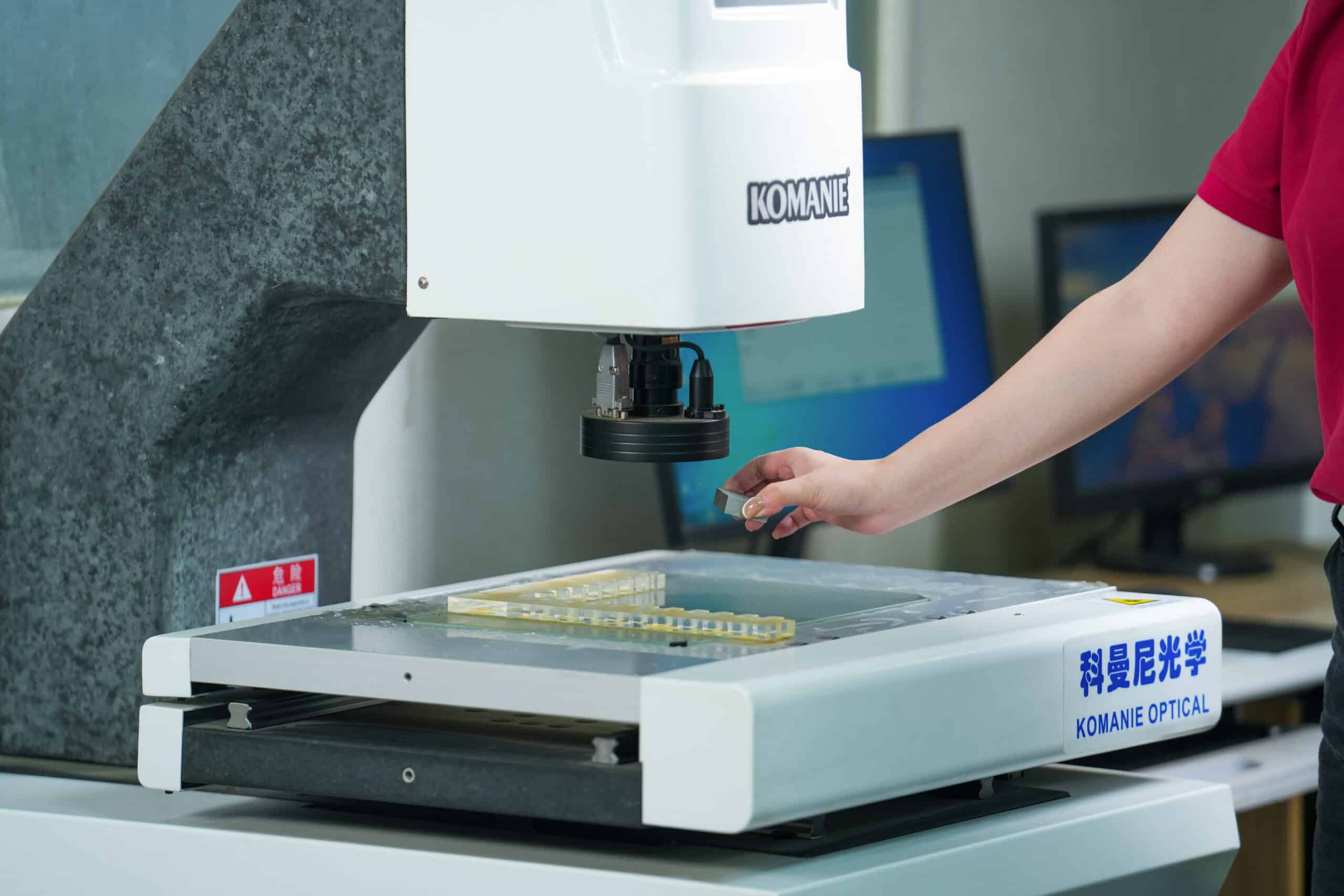
Dimensional Accuracy
Using advanced CMM (Coordinate Measuring Machines), digital micrometers, and optical measurement systems, we inspect all critical features of your parts with micrometer-level precision. This guarantees that each part meets its specified dimensions and tolerances, ensuring optimal functionality and fit.
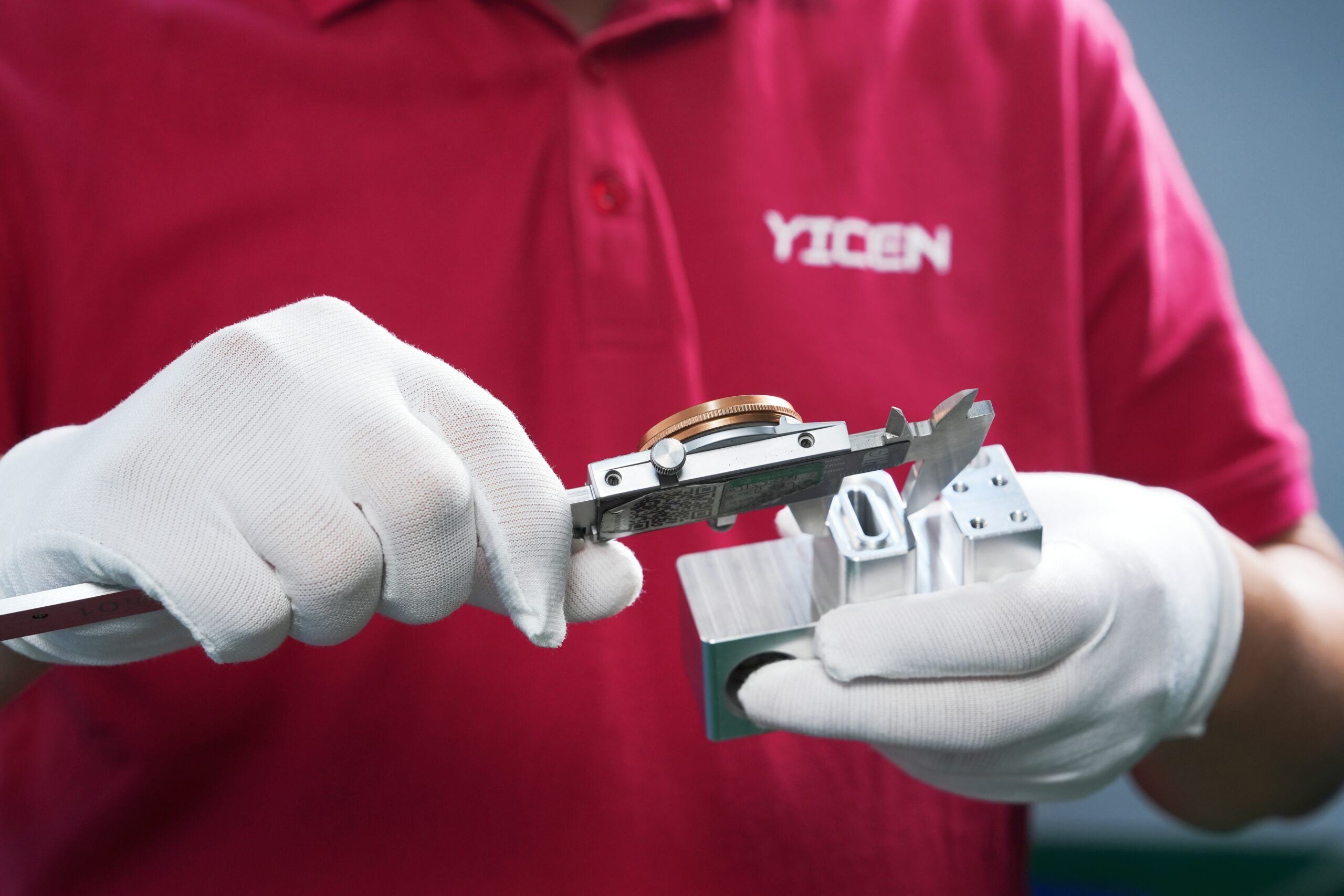
Visual Inspection
Our experienced technicians visually inspect each component to check for surface defects, burrs, or any other imperfections that could affect the quality and performance of the part. This additional layer of inspection ensures that parts are free from cosmetic and functional flaws.
Mechanical Testing (If Required)
For components that require additional validation, we offer mechanical testing to verify strength, durability, and other material properties. This can include tensile testing, hardness testing, and more, depending on the specific requirements of your parts.
Material Traceability
Every part produced at Yicen Precision is accompanied by complete material traceability. We provide material certificates (MTRs), First Article Inspection (FAI) reports, and CMM data sheets to ensure full transparency in the manufacturing process, giving you confidence in the quality and source of your materials.
Easily upload your CAD files through our secure online platform to get started.
Customize Your Requirements
Choose your material, finish, tolerances, and preferred lead time to match your project needs.
Get an Instant Quote
Receive a real-time quote based on your design and selected specifications, no delays.
Production & Delivery
Your parts are manufactured by trusted partners, quality-checked, and delivered to your door on time.
Why Choose Us for DMLS Services?
At Yicen Precision, we offer world-class Direct Metal Laser Sintering (DMLS) services that combine cutting-edge technology with years of expertise. Here’s why we’re the ideal choice for your next metal additive manufacturing project.
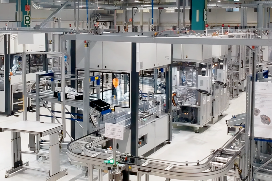
Industrial DMLS Equipment
We use state-of-the-art DMLS machines, capable of producing high-precision, fully dense metal parts. Our equipment ensures superior quality, efficiency, and fast turnaround times, even for complex designs.
Metal Additive Expertise
With years of experience in metal additive manufacturing, we have perfected the art of DMLS to deliver parts that meet the highest industry standards for strength, performance, and reliability.
Integrated Machining & Finishing
We offer integrated machining and finishing services to refine your parts post-printing. This ensures that your parts not only meet dimensional and functional specifications but also possess the desired surface finish for your applications.
Prototype & Production Support
Whether you need rapid prototyping or high-volume production, our DMLS services support both. We are capable of producing parts that go from concept to full-scale production quickly and efficiently, minimizing lead times.
Engineering Assistance
Our experienced engineers work closely with you to ensure that your designs are optimized for DMLS. From material selection to design adjustments, we provide full engineering support to ensure your parts are manufactured efficiently and accurately.
Unmatched Precision and Quality
We guarantee consistent quality and tight tolerances for every part produced. Our quality assurance processes ensure that every part meets the highest standards, giving you confidence in the performance and durability of your components.
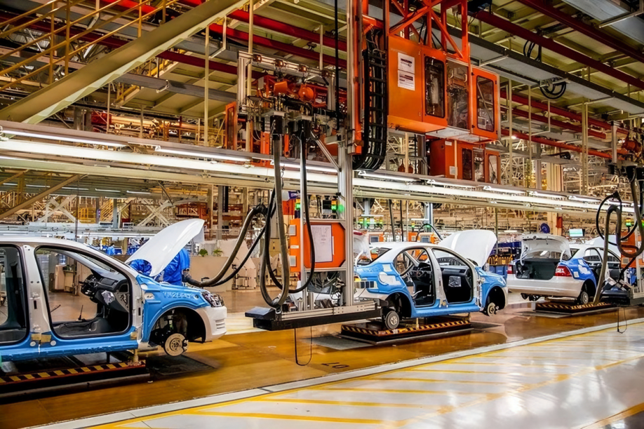
Industries We Serve
Yicen Precision is serving a broad spectrum of industries, covering aerospace, automotive, electronics, medical, and more. We specialize in providing high-quality, reliable parts tailored to meet the unique engineering challenges of each industry.
DMLS brings numerous advantages to manufacturing, providing solutions that are efficient, cost-effective, and capable of producing complex geometries and fully dense metal parts.
Fully Dense Metal Parts: DMLS produces parts with excellent mechanical properties and high density, making them suitable for demanding applications.
Complex Internal Geometries: The ability to create complex internal features, such as channels and lattices, reduces part count and enhances functionality.
Part Consolidation: Multiple components can be consolidated into a single part, reducing assembly time and material costs.
No Tooling Required: DMLS eliminates the need for traditional tooling, allowing for more flexible design changes and faster iterations.
Faster Time to Market: With DMLS, parts can be produced much faster than with traditional methods, significantly reducing lead times and time to market.
Applications
Applications of Direct Metal Laser Sintering (DMLS)
Direct Metal Laser Sintering (DMLS) is revolutionizing industries by enabling the creation of high-precision, complex metal parts that are critical for modern manufacturing. This versatile process is widely used across various sectors for producing functional parts, prototypes, and custom components.
Rapid Tooling & Fixtures: DMLS is ideal for creating rapid tooling and production fixtures, offering fast lead times and high precision for prototype and small batch runs.
Functional Prototypes: Quickly turn concepts into functional prototypes that test form, fit, and function, reducing design iterations and improving product validation.
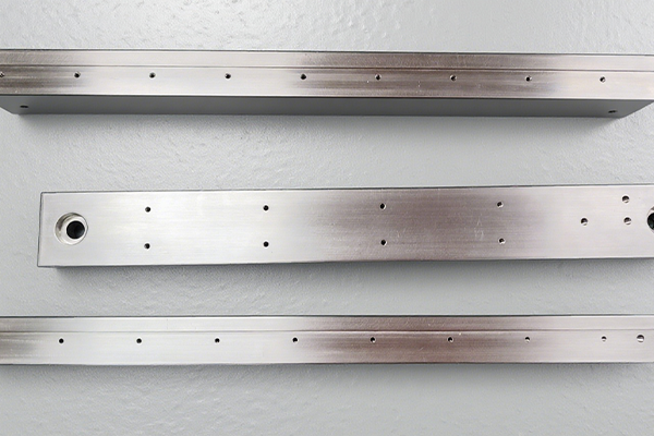
End-Use Metal Components: DMLS allows for the production of durable, high-performance parts that are ready for end-use applications in critical industries like aerospace and automotive.
Lightweight Structural Parts: Through the use of lattice structures and complex geometries, DMLS produces lightweight, strong structural parts suitable for industries where weight reduction is essential, like aerospace.
Complex Internal Channel Designs: DMLS is capable of producing intricate internal features like cooling channels, which are difficult to manufacture using traditional methods, making it ideal for high-performance applications.
Connect With Us
Transform Concepts into Precision Parts
We specialize in converting your ideas into high-quality, functional components with unparalleled speed and accuracy. With advanced technology and expert craftsmanship, we create parts that meet the most complex specifications.
For optimal DMLS parts, ensure your designs avoid sharp internal angles, keep wall thickness consistent, and consider part orientation for strength. Our engineering team is available to help optimize designs for the best results.
What are the advantages of DMLS over traditional manufacturing?
DMLS offers advantages such as complex geometries (including internal channels), no tooling requirements, and faster time-to-market. It’s ideal for applications requiring complex shapes that are difficult or impossible to achieve using traditional manufacturing methods.
What are the typical lead times for DMLS?
DMLS offers fast lead times, typically ranging from 1 to 3 days for prototypes and 5 to 10 days for small batch production. Lead times may vary depending on part complexity and finishing requirements.
Does DMLS require post-processing?
While DMLS parts are functional as printed, post-processing such as bead blasting, machining, or polishing is often required to achieve the desired surface finish and precision. Post-processing enhances the appearance, accuracy, and surface quality.
What materials are available for DMLS?
DMLS supports a wide range of metal materials, including stainless steel (17-4 PH, 316L), titanium (Ti6Al4V), aluminum (AlSi10Mg) and Inconel 718. Each material is selected based on its intended application, offering excellent strength, corrosion resistance, and thermal properties.