A robot is only as good as its weakest joint. You can write perfect control code, but if a bearing bore runs a few hundredths out of position, the arm will wobble, wear and drift. That is why robotics CNC machining sits at the center of so many builds, from small lab prototypes to production cells on a factory floor. This guide covers which parts get machined, which materials work, how tight tolerances need to be and what design choices save money.
Where CNC Machining For Robotics Fits in the Build
Robots move, and moving parts demand accuracy. Machined parts give you repeatable geometry, tight fits and a surface finish that bearings and seals actually like. Casting and 3D printing both have a place, but neither matches a milled or turned part when two surfaces must line up exactly.
CNC also suits the way robots get developed. Early designs change often. Machining needs no tooling, so you can revise a drawing on Monday and hold a new part by the end of the week. Once the design settles, the same program scales from five units to five hundred.
[Add 2 lines here: a robotics project you machined, and what the customer needed most.]
Robot Arm Components That Start on a Mill
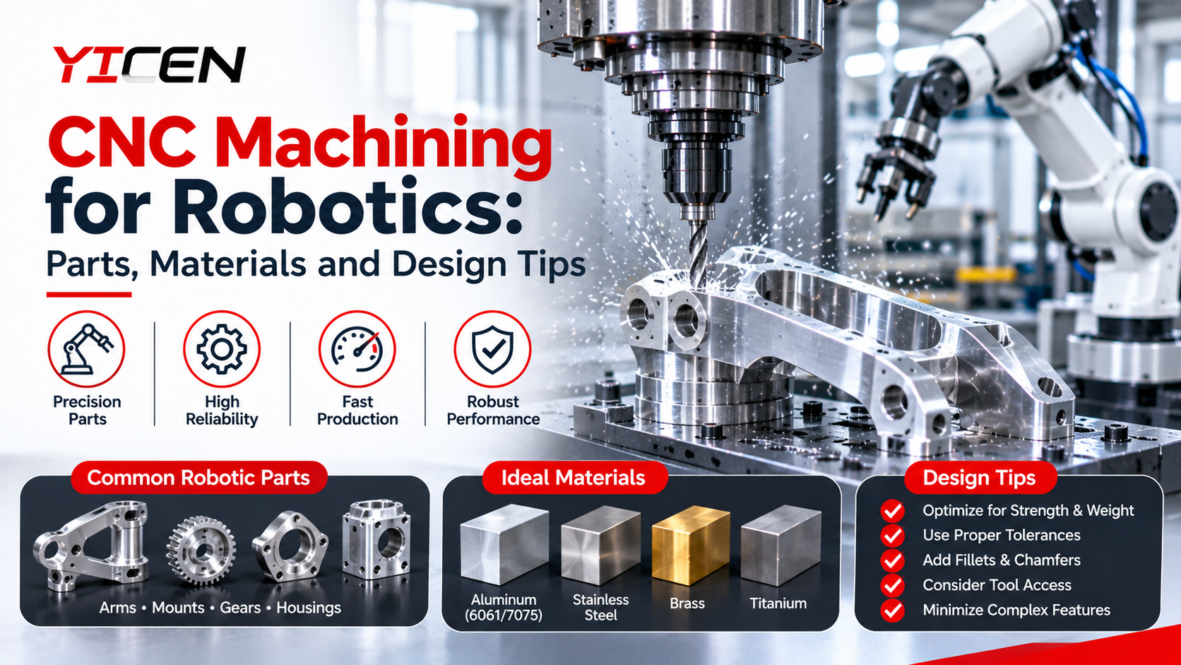
Robot arm components make up the biggest share of machined robotics work. Each one has a job, and each one punishes mistakes differently.
- Links and arm segments. These carry load and must stay stiff while weighing as little as possible. Pocketing removes material without losing strength.
- Joint housings. They hold bearings and motors in line. Bore position and concentricity matter most here.
- Gearbox and reducer parts. Gear carriers, flanges and output plates need flat faces and accurate pilot diameters.
- Base plates and mounts. They anchor everything, so flatness and hole position drive the whole assembly.
- Shafts and couplers. Turned parts with tight diameters and clean shoulders keep power moving without backlash.
Grippers and end effectors add another layer. Fingers, jaws and tool plates often change from job to job, which makes them ideal for short-run machining.
Choosing Materials for Lightweight Robotic Parts
Weight hurts a robot twice. Heavier arms need bigger motors, and bigger motors add more weight. So lightweight robotic parts usually decide how fast, how far and how efficiently a machine can move.
Aluminum is the usual starting point. It cuts easily, finishes well and offers strong stiffness for its weight. If you’re torn between grades, our comparison of Aluminium 6061 im Vergleich zu 7075 lays out strength, cost and machining differences in plain terms.
| Material | Am besten für | Watch out for |
|---|---|---|
| 6061 Aluminium | Frames, housings, brackets | Lower strength than 7075 |
| 7075 aluminum | Highly loaded links and plates | Higher cost, welding limits |
| Rostfreier Stahl | Shafts, food or wash-down robots | Weight, slower cutting |
| Titan | Premium, weight-critical parts | Cost and tool wear |
| Engineering plastics (POM, PEEK) | Bushings, insulators, grippers | Lower stiffness, heat limits |
Plastics deserve more credit than they get. Acetal makes a quiet, low-friction bushing. PEEK handles heat and chemicals where other plastics give up. Carbon fiber sheet can be machined too, though it needs the right tooling and dust control.
One more thing about material choice: pick it with the finish in mind. Anodizing protects aluminum and adds wear resistance, but it adds a small amount of thickness. Plan for that on press fits and sliding surfaces.
Tolerances That Keep Joints Honest
Not every dimension needs to be tight, and treating them all that way burns money. Spend your precision where motion happens.
As a rough guide, bearing bores often sit in the range of plus or minus 0.01 mm or better, depending on the bearing and the fit you want. Locating pins and dowel holes commonly run near plus or minus 0.01 to 0.02 mm. General outer surfaces can relax to plus or minus 0.1 mm. Your bearing supplier’s fit tables and your own load case should set the final numbers.
Geometric tolerances matter just as much as size. Concentricity between two bearing seats, perpendicularity of a flange to a bore and flatness of a mounting face can each decide whether a joint spins freely or binds. Call them out on the drawing only where the function needs them.
Custom Robotic Parts: Design Tips That Cut Cost
Custom robotic parts don’t have to be expensive. Most of the savings come from small choices made before the file is sent.
- Fügen Sie an den Innenecken Rundungen hinzu. A tool is round, so a sharp internal corner forces slow, small cutters. A generous radius lets the shop use a bigger tool and finish sooner.
- Keep wall thickness sensible. Thin walls vibrate during cutting and can warp afterward. Hold them above roughly 1 mm in aluminum when you can.
- Limit deep, narrow pockets. Depth beyond about four times the tool diameter slows everything down.
- Standardize hole sizes and threads. Fewer tool changes mean lower cost and faster delivery.
- Design for one or two setups. Every time a part gets flipped, you add time and a chance for small errors.
- Mark critical features only. If everything is “critical,” nothing is.
Think about assembly, too. Add small chamfers for easy bearing insertion, include witness features for alignment and leave tool access for fasteners. A part that is easy to build is usually easy to service in the field.
Finishes and Inspection That Matter
Surface treatment does real work on a robot. Anodizing adds corrosion resistance and a hard surface. Black oxide helps steel shafts. Passivation protects stainless. For sliding surfaces, a fine ground or turned finish often beats a coating.
Inspection matters just as much. A coordinate measuring machine (CMM) report on bores, hole patterns and flatness gives you proof before the part ever reaches your bench. For production runs, ask for first article inspection so the whole batch matches an approved sample.
Industries Pushing the Demand
Machined parts for robots serve more than one market. Factory cells, packaging lines and inspection stations all rely on accurate, durable hardware, and the Automatisierungsbranche keeps raising the bar on repeatability. Meanwhile, teams that need Robotikteile for research, service or logistics robots want short lead times and small batches. A good machining partner handles both without changing the process.
Choosing a Partner for Your Next Build
Look for a shop that asks questions about your design instead of just quoting it. They should talk about fits, tolerances, materials and finishing before they talk about price. If you’d like to know who we are and how we work, read more about our company.
Ready to move forward? Send us your drawings, material grade and quantity, and we’ll review your CNC machining for robotics project for manufacturability before any chips fly. You’ll get a clear quote and honest notes on where a small change could save time or money. You can also reach out to our team with early concept files if the design isn’t final.
Häufig gestellte Fragen
Which robot parts are made by CNC machining?
Common machined parts include arm links, joint housings, gearbox plates, base mounts, shafts and gripper fingers. Any part that needs accurate fits or tight positions is a good candidate.
What materials suit lightweight robotic components?
Aluminum 6061 and 7075 lead the list for strength and low weight. Titanium suits premium builds, and plastics like POM and PEEK work well for bushings and grippers.
How tight should robot joint tolerances be?
Bearing bores often need around plus or minus 0.01 mm, while non-critical surfaces can be looser. Check your bearing’s fit tables and tighten only what affects motion.
Is CNC machining for robotics worth it for prototypes?
Yes. It needs no tooling, so design changes cost little and parts arrive fast. You also test the same material and accuracy you’ll use in production.
Verändert das Eloxieren die Abmessungen der Teile?
Slightly. It adds a thin layer, usually a few microns for Type II. Tell your machinist which surfaces are press fits so they can compensate.