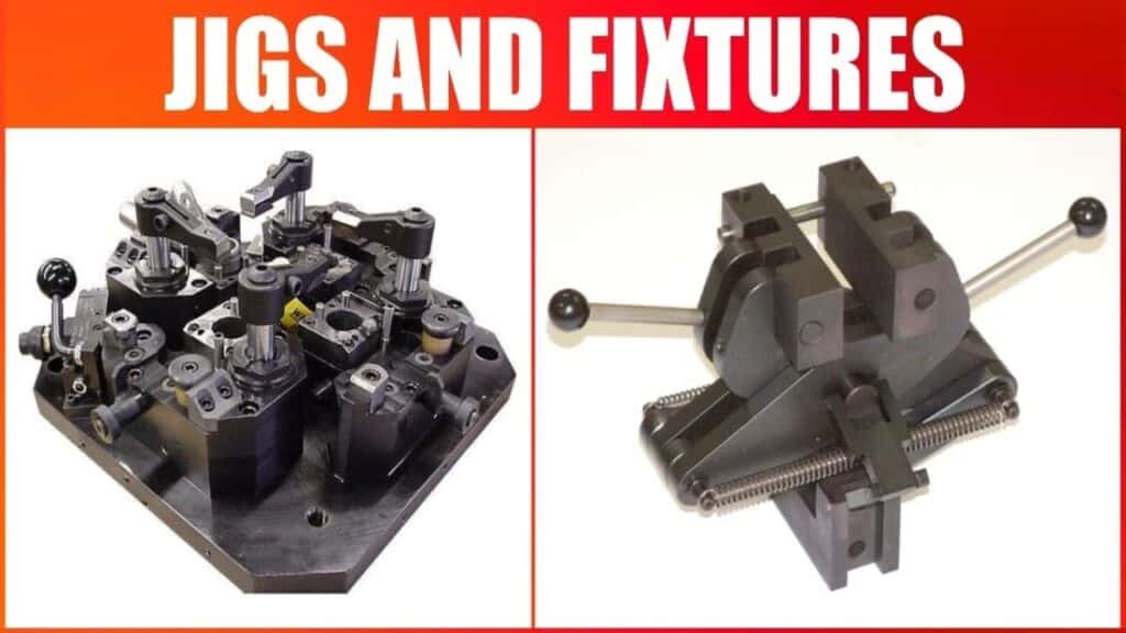
What Are Locating and Clamping Devices?
Locating and clamping devices are essential components in Jig and Fixture design, ensuring that workpieces are accurately positioned and securely held during machining, assembly, or inspection. These devices are critical for achieving precise manufacturing results, reducing errors, and enhancing productivity.
Definition of Locators in Jig & Fixture Design
Locators are devices used to position a workpiece accurately within a fixture or jig. Their primary function is to establish a reference point or plane, ensuring that the part is held in a fixed, repeatable position throughout the manufacturing process. Locators are the foundation for achieving dimensional accuracy and uniformity in production.
Definition of Clamping Devices
Clamping devices are used to hold the workpiece firmly in place once it has been properly located. The primary role of clamping is to resist the forces applied during machining, preventing part movement or distortion. Clamps are designed to securely hold the workpiece while minimizing deformation and damage to the part, ensuring the process runs smoothly and accurately.
Why Locating Comes Before Clamping (Engineering Principle)
In engineering, the principle of locating before clamping is fundamental. The workpiece must first be accurately located using locators to ensure precise positioning. Once the part is correctly located, clamping can be applied to hold the part securely in place. Locating first prevents any misalignment that could occur if the part were clamped before it was positioned correctly. This sequence ensures that the clamping forces are applied only after the part is in its optimal orientation, reducing the risk of distortion or incorrect positioning.
Purpose & Importance
How Locators Ensure Repeatability
Locators are essential for repeatability in manufacturing. They ensure that every workpiece is placed in the exact same position each time, which is crucial for maintaining consistent product quality. Accurate locating devices reduce variability in production, leading to fewer defects and more reliable outcomes in machining processes.
How Clamps Maintain Stability Under Cutting Forces
Clamps are critical for maintaining the stability of the workpiece during cutting, Wenden, or other machining operations. The forces generated by cutting tools can cause parts to shift, which may result in inaccuracies or even damage. Clamps counteract these forces by holding the workpiece securely in place, allowing for precise machining and reducing the risk of part distortion.
Impact on Cycle Time, Tolerances & Tool Life
The design of locating and clamping devices has a direct impact on cycle time, tolerances, and tool life. Well-designed devices reduce setup time, ensuring faster production cycles. Accurate locators minimize tolerance variations, which is crucial for producing high-quality parts that meet stringent specifications. Additionally, effective clamping reduces wear on tools by preventing workpiece movement, extending tool life and reducing the frequency of tool changes.
Role in Lean Manufacturing & Precision CNC Operations
In lean manufacturing, the goal is to eliminate waste and optimize processes. Locating and clamping devices play a key role by improving efficiency, reducing downtime, and ensuring that parts are machined correctly the first time. In precision CNC-Bearbeitung, where high accuracy is required, these devices are essential for ensuring that parts are held securely and consistently during every cycle.
Basic Principles of Locating in Jigs and Fixtures
3-2-1 Principle Explained (Primary, Secondary, Tertiary Locators)
Die 3-2-1-Prinzip is a widely used method for locating a workpiece in a fixture. It ensures that a workpiece is properly constrained along all three axes—X, Y, and Z.
- Primary Locators: These control the position along one axis, typically placed on the largest, flattest surface of the part.
- Secondary Locators: These control two more axes, generally placed on the second-largest surface.
- Tertiary Locators: These constrain the final axis and ensure that the part is positioned correctly in all directions.
Degrees of Freedom (6 DOF)
In three-dimensional space, a rigid body has six degrees of freedom: three translational movements (X, Y, Z) and three rotational movements (pitch, yaw, roll). Locators work by constraining specific degrees of freedom, preventing the workpiece from moving or rotating in undesirable ways. Effective locating minimizes these freedoms to ensure that the workpiece stays fixed in the required orientation.
Avoiding Redundant Location
Redundant locating occurs when excessive locators are used, causing unnecessary constraints on the workpiece. This can lead to deformation or undue stress on the part, which may negatively affect machining accuracy. It’s essential to use the correct number of locators based on the part’s geometry and the required machining operation.
Proper Locator Placement for Machining Forces
Locators must be placed in areas where they will not interfere with machining operations. They should be positioned to withstand the forces generated by cutting tools without causing distortion in the workpiece. Locators should also be positioned to prevent any vibration, which could affect machining accuracy.
Locating Accuracy vs. Fixture Cost Optimization
While accurate locating is essential for high-quality manufacturing, the cost of fixtures should also be considered. More complex locator systems may offer higher precision but can also increase fixture cost and manufacturing time. Engineers must strike a balance between achieving the desired accuracy and managing costs to optimize production efficiency.
Types of Locating Devices
Flat Locators
Flat locators are used to support the workpiece along flat surfaces, ensuring that the part is positioned parallel to the fixture. They are commonly used in milling and drilling operations for parts with flat faces.
Cylindrical Locators / Pin Locators
Cylindrical pin locators are used for parts with round geometries. These locators fit into corresponding holes or slots in the workpiece, ensuring proper alignment. Pin locators are often used for locating cylindrical parts in turning or milling operations.
Round & Diamond Locating Pins
Round and diamond-shaped pins are used for more complex geometries, especially when precise positioning is required. These pins are ideal for parts with irregular or non-flat surfaces, providing secure and repeatable location.
Rest Pads & Support Blocks
Rest pads and support blocks are used to provide additional stability and support for the workpiece. These are particularly useful for parts that need to be held in a certain orientation during the machining process, such as during drilling or grinding.
V-block Locators (for round parts)
V-block locators are designed for cylindrical workpieces. The V-shape cradles the part securely, ensuring accurate positioning for operations like turning or milling.
Adjustable Locators / Spring-loaded Locators
Adjustable locators allow for flexibility in fixture design, accommodating parts with varying dimensions. Spring-loaded locators automatically adjust to the size of the workpiece, providing a secure hold while compensating for slight variations in part size.
Nesting Locators for Complex Shapes
Nesting locators are used for workpieces with complex or irregular shapes. They “nest” into the contours of the part, ensuring that it is positioned correctly for machining without the need for additional supports.
Locating Device Selection Guidelines
Tolerance Stack-Up Considerations
When selecting locating devices, engineers must account for tolerance stack-up, which occurs when slight inaccuracies from various components accumulate. Choosing locators that can compensate for these variations ensures that the final product meets tight tolerance requirements.
Choosing Locator Material (Tool Steel, Carbide, Hardened Steel)
The material of the locator must be selected based on the wear resistance required for the specific application. Tool steel, carbide, and hardened steel are common Materialien due to their durability and ability to maintain precision over time. The material choice depends on factors such as the workpiece material, the machining process, and the expected production volume.
Workpiece Material Effects (Aluminum, Steel, Cast Iron)
Different workpiece materials affect the choice of locator material. For example, softer materials like aluminum may require locators with softer contact surfaces, while harder materials like steel or cast iron may require more robust locator materials to withstand wear and tear.
Chip Clearance & Accessibility Factors
Locators should be designed with adequate chip clearance to prevent debris buildup, which could interfere with the machining process. The accessibility of locators is also essential to ensure that the workpiece can be easily loaded and unloaded from the fixture.
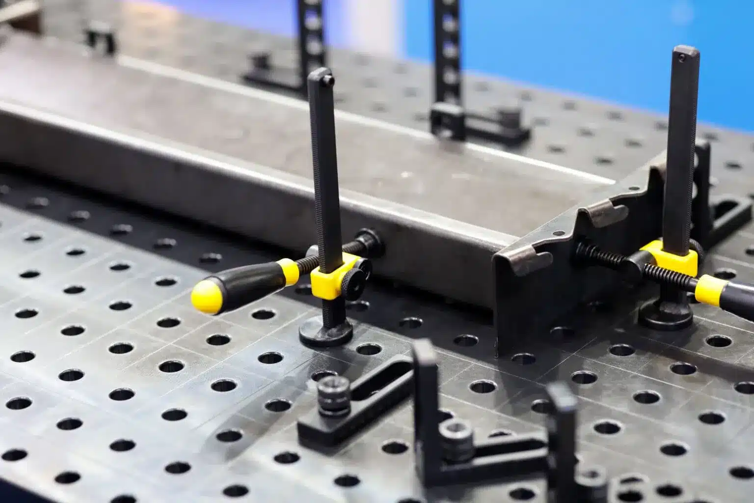
Clamping Devices in Jigs & Fixtures
What Is Clamping? (Definition & Function)
Clamping is the process of securing a workpiece to a fixture or jig to prevent movement during machining, assembly, or inspection. Effective clamping ensures that the part remains stable under cutting forces, preventing deformation and ensuring accurate results.
How Clamping Prevents Workpiece Movement
Clamps exert force on the workpiece to hold it securely against locators. The force applied by the clamp counteracts the cutting forces generated during machining, preventing the part from shifting, vibrating, or deforming.
Clamping Force Direction Relative to Locators
The clamping force should be applied in a direction that complements the locator system. The force must be directed to hold the workpiece against the locators without distorting the part or creating excessive pressure on any specific area.
“Holding vs. Distortion” — Avoiding Workpiece Warping
When clamping, it is crucial to strike a balance between holding the workpiece securely and avoiding excessive force that could cause warping. Properly designed clamps ensure that the workpiece is firmly held in place without inducing unwanted stresses or deformation.
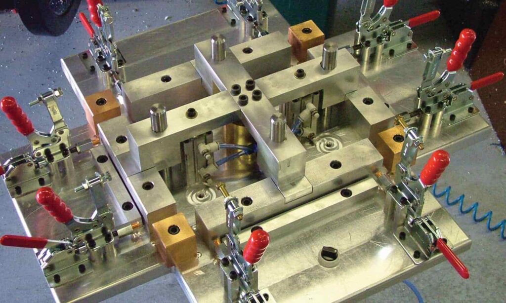
Types of Clamping Devices
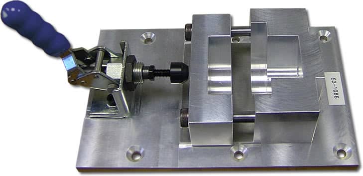
Manual Clamping Devices
Manual clamping devices rely on human force to secure the workpiece. Examples include:
- Toggle clamps: Provide fast and reliable clamping force with minimal effort.
- Strap clamps: Secure parts along edges, especially useful for irregularly shaped parts.
- Screw clamps: Used for precision work, providing fine control over the clamping force.
- Edge clamps: Ideal for securing parts along their edges.
- Cam clamps: Offer quick and easy clamping with high force.
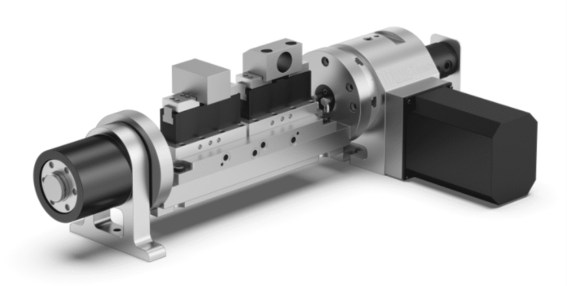
Power-Operated Clamps
Power-operated clamps use hydraulic, pneumatic, or motorized systems to apply clamping force, providing greater speed and consistency in automated environments. These include:
- Hydraulic clamps: Provide adjustable clamping force, often used in high-production environments.
- Pneumatic clamps: Use compressed air to clamp parts quickly and efficiently.
- Swing clamps: Allow for easy adjustment and application of clamping force.
- Magnetic clamps: Provide non-contact clamping for delicate parts.
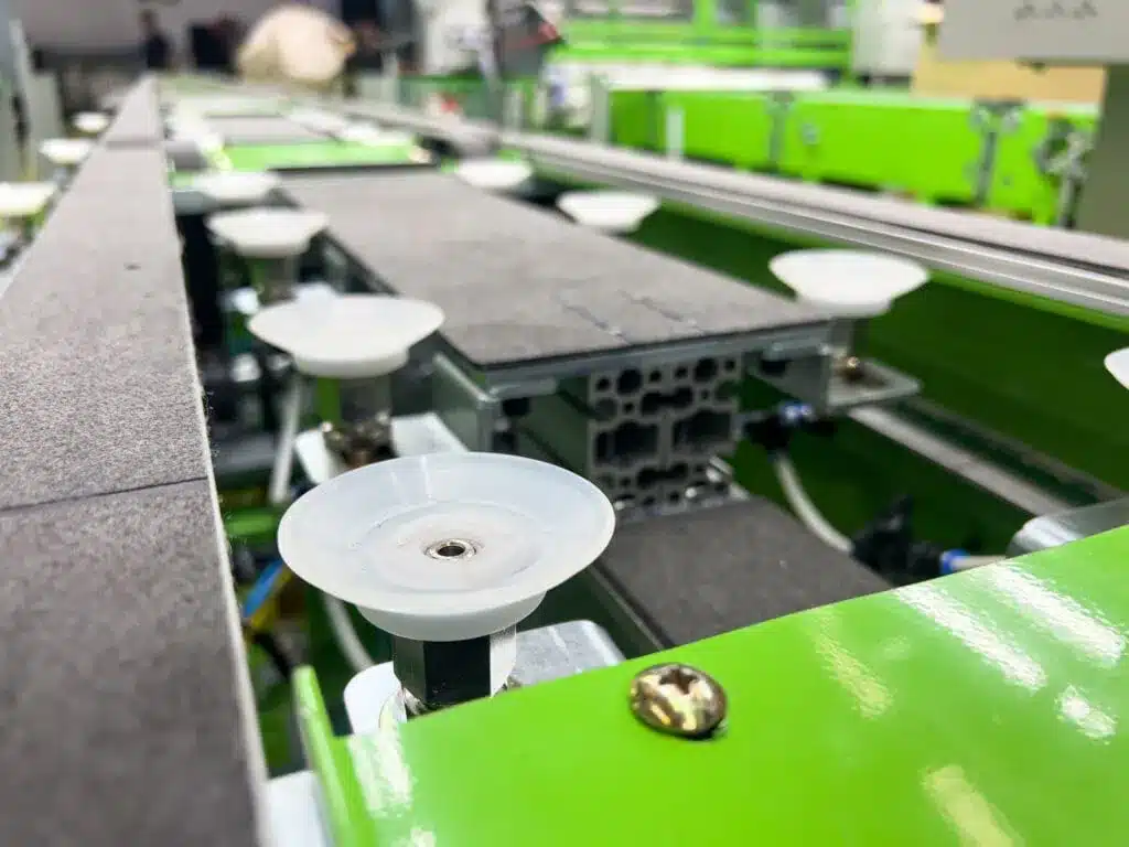
- Vacuum clamping systems: Ideal for flat or flexible parts, using suction to hold the workpiece securely.
Special-Purpose Clamps
Special-purpose clamps are designed for specific applications, such as:
- Modular fixturing clamps: Adaptable clamps for modular fixture systems.
- Quick-release clamps: Enable rapid part changeover in high-volume production.
- Self-adjusting clamps: Automatically adjust to accommodate variations in workpiece dimensions.
Clamping Principles (Engineering Basics)
Clamping Force Calculation
Clamping force must be calculated based on the workpiece material, cutting forces, and desired level of security. Inadequate clamping force can lead to part movement, while excessive force may cause deformation.
Force Direction & Workpiece Behavior
The direction of the clamping force is crucial to prevent distortion. Clamps should apply force in a way that doesn’t induce bending or twisting of the workpiece.
Avoiding Workpiece Damage (Pads, Bushings, Soft Jaws)
To prevent damage to delicate parts, clamps should include soft pads, bushings, or soft jaws that distribute the clamping force evenly and reduce the risk of marking or deforming the workpiece.
Vibration Resistance & Stability
Clamps must be designed to resist vibrations caused by cutting forces. Vibration can lead to inaccuracies in Bearbeitung, so clamps should provide a stable and rigid hold to prevent movement during operation.
Accessibility for Loading & Unloading
Clamps should be designed for easy access to facilitate quick and safe loading and unloading of workpieces. The clamp mechanism should allow operators to insert or remove parts with minimal effort.
Locating & Clamping Integration
How Locators + Clamps Work Together
Locators and clamps must work in tandem to ensure the part is accurately positioned and securely held. Locators position the workpiece with precision, while clamps apply the necessary force to keep it in place during machining.
Preventing Fixture Distortion
By properly integrating locators and clamps, designers can ensure that the fixture doesn’t distort during the machining process. This integration prevents errors that may arise from incorrect part positioning or excessive clamping force.
Balancing Force Distribution
Balancing the distribution of clamping force is essential for avoiding part distortion and ensuring consistent part quality. The forces from clamps should be evenly applied to prevent any area from being under or over-constrained.
Aligning with Machining Forces (Drilling, Milling, Turning)
Locators and clamps should be aligned with the direction of machining forces to maintain stability during cutting, drilling, milling, or turning operations. Proper alignment ensures that forces from the cutting tool don’t cause the part to shift or deform.
Common Mistakes and How to Avoid Them
Over-Clamping
Excessive clamping force can cause part distortion or damage. Engineers should carefully calculate the required clamping force based on material properties and machining conditions.
Redundant Locating
Using too many locators can introduce unnecessary constraints, leading to part distortion. It’s essential to follow the 3-2-1 principle and avoid over-constraining the part.
Poor Clamp Placement
Incorrect clamp placement can cause parts to shift or deform during machining. Ensure clamps are positioned to resist the forces generated by the cutting tools without interfering with the machining process.
Using Wrong Materials
Selecting the wrong materials for locators or clamps can lead to premature wear or failure. Use materials that are compatible with the workpiece and the machining environment.
Lack of Chip Clearance
Inadequate chip clearance can lead to debris buildup, interfering with machining operations. Ensure locators and clamps are designed to allow for proper chip removal during operations.
Real-world Jig & Fixture Clamping/Locating Examples
Drill Jig Clamp & Locator Setup
A drill jig uses a cylindrical pin locator to position a part accurately while a toggle clamp holds the workpiece securely during drilling operations.
Milling Fixture Locating Pins + Swing Clamp
In a milling fixture, round locating pins ensure accurate positioning, while a swing clamp holds the workpiece in place as the cutter removes material.
V-Block + Strap Clamp for Cylindrical Parts
A V-block locator is used to hold cylindrical parts in place while a strap clamp secures the workpiece, ensuring stability during machining.
Hydraulic Clamping in Automotive Fixture
In an automotive fixture, hydraulic clamps apply uniform force to secure large components, ensuring precision during high-volume manufacturing.
Engineering Drawings: Locators & Clamps
Standard Symbols & Annotations
Engineering drawings should use standard symbols and annotations to represent locators and clamps, ensuring clear communication of design intent.
GD&T Considerations for Locators
Geometric Dimensioning and Tolerancing (GD&T) is used to specify the allowable variation in part location and orientation, ensuring that locators are accurately positioned relative to the part.
Callouts for Clamping Devices
Callouts for clamping devices should specify the type of clamp, its location, and any relevant details such as clamping force or adjustment capabilities.
Exploded View & BOM (Bill of Materials) Best Practices
An exploded view of the fixture and a Bill of Materials (BOM) should be included in engineering drawings to help with assembly, maintenance, and procurement of components.
Best Materials for Locating & Clamping Devices
Tool Steel (D2, O1, A2)
Tool steel is commonly used for locators and clamps due to its hardness, wear resistance, and ability to maintain dimensional accuracy under high-stress conditions.
Carbide-Tipped Locators
Carbide-tipped locators provide superior wear resistance and are ideal for high-precision applications where tool longevity is crucial.
Hardened Steel vs. Mild Steel Components
Hardened steel is used for high-durability applications, while mild steel is more cost-effective and suitable for less demanding tasks.
Soft Pads & Nylon Inserts for Delicate Parts
For delicate parts, soft pads or nylon inserts are used to protect the workpiece from damage during clamping, ensuring that no markings or scratches occur during the process.
Modern & Smart Locating/Clamping Systems
Modulare Vorrichtungssysteme
Modular fixturing systems offer flexibility by allowing users to quickly adjust or reconfigure fixture setups for different parts.
Zero-Point Clamping Systems
Zero-point clamping systems provide quick setup times and high precision by using predefined positions on the machine for rapid part exchange.
Smart Hydraulics & Load Sensors
Smart hydraulic systems use load sensors to provide real-time feedback on clamping force, ensuring optimal performance and minimizing the risk of over-clamping.
Automation & Robot-Friendly Clamps
Automation-friendly clamps are designed to work seamlessly with robotic arms and other automated systems, enabling fully automated production lines.
Checklist for Engineers — Locating & Clamping Design
- DoF Controlled? Ensure all six degrees of freedom (translation and rotation) are properly constrained.
- Proper Locator Contact? Verify that locators are in contact with the workpiece at the right points.
- Clamp Force Adequate? Ensure that clamping force is sufficient to hold the workpiece securely without causing distortion.
- No Workpiece Deformation? Check that the workpiece remains undamaged throughout the machining process.
- Easy Loading/Unloading? Design the fixture for quick and safe loading/unloading.
- Safe for Operators? Ensure all components are designed for operator safety, including ergonomic considerations.
Schlussfolgerung
Locators position the workpiece with high precision, while clamps ensure it stays securely in place during machining. Together, these components play a vital role in achieving accurate, repeatable, and high-quality manufacturing outcomes.
Importance in Manufacturing Precision
The combination of well-designed locating and clamping devices is crucial in precision manufacturing. These devices ensure that parts are machined with high accuracy and minimal variation, making them essential for producing high-quality, reliable products.
FAQs on Locating & Clamping Devices
What is the difference between locators and clamps?
Locators position the workpiece in a fixture, ensuring that it is accurately aligned before machining. Clamps hold the workpiece in place after it has been positioned by the locators, preventing movement during machining. The key difference is that locators focus on positioning, while clamps focus on securing the part during operation.
Which clamp type is best for CNC milling?
For CNC milling, toggle clamps und hydraulic clamps are commonly used. Toggle clamps offer fast clamping and easy adjustment, while hydraulic clamps provide adjustable force and are ideal for high-volume, automated processes.
Difference between locating and clamping?
Locators position the workpiece precisely. Clamps hold it securely against the locators during machining.
How to determine clamping force?
Use 2–3 times the expected cutting force. Always clamp toward heavy sections and solid locators to avoid distortion.