
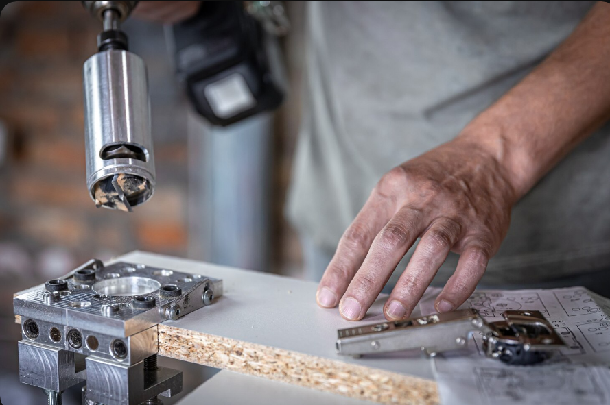
High-speed milling is not spinning the tool faster. It is a different way of loading the cutter: high spindle speed combined with a light radial engagement and a high feed rate, taking small chips very quickly instead of large chips slowly. The result is that most of the heat leaves in the chip rather than soaking into the tool or the workpiece, which is why tool life often improves at higher speeds rather than collapsing.
That change in loading has consequences all the way through the process, and the one that catches people out is the arithmetic. A light radial cut thins the chip, so running the same feed per tooth you would use for a conventional cut actually rubs the material rather than cutting it. This guide covers the parameters, the correction that makes them work, tool and holder selection, and how the choices translate into the surface finish on the part.
What defines a high-speed cut
Three parameters describe any milling cut, and high-speed milling changes the balance between them rather than any single value.
| Parámetro | Meaning | Conventional milling | Fresado de alta velocidad |
| Cutting speed (vc) | Surface speed at the tool edge | Moderado | Alta |
| Feed per tooth (fz) | Material each flute removes per revolution | Moderado | Moderate to high, corrected for thinning |
| Radial depth (ae) | Width of cut across the tool | Often 50 to 100 percent of diameter | Typically 5 to 15 percent of diameter |
| Axial depth (ap) | Depth of cut along the tool axis | Shallow | Often the full flute length |
The last two rows are the real signature of the technique. A conventional roughing cut takes a shallow but wide bite; a high-speed cut takes a narrow but deep one. Engaging the full flute length spreads wear along the whole cutting edge instead of concentrating it in one band, and the small radial engagement keeps cutting forces low enough that a slender tool can run at feed rates that would break it in a wide cut.
The two calculations everything else depends on:
Spindle speed: n (rpm) = (vc × 1000) ÷ (π × D)
Feed rate: vf (mm/min) = fz × number of flutes × n
Where vc is cutting speed in metres per minute and D is tool diameter in millimetres. These are the starting point, not the finish, because of what happens to chip thickness at light radial engagement.
Radial chip thinning: the correction most people skip
When radial engagement is less than half the tool diameter, the actual thickness of the chip produced is smaller than the programmed feed per tooth. The flute enters and exits the material through a shallow arc, so it never reaches the full commanded bite.
The chip thinning factor is:
Chip thinning factor = 2 × √( (ae ÷ D) − (ae ÷ D)² )
Multiply your programmed feed per tooth by that factor and you get the chip the tool is actually producing. To restore the chip to the thickness the tool was designed for, divide the intended feed per tooth by the factor.
| Radial engagement (ae) | ae ÷ D | Thinning factor | Feed correction |
| 50% of diameter | 0.50 | 1.00 | None needed |
| 30% of diameter | 0.30 | 0.92 | Multiply feed by 1.09 |
| 20% of diameter | 0.20 | 0.80 | Multiply feed by 1.25 |
| 10% of diameter | 0.10 | 0.60 | Multiply feed by 1.67 |
| 5% of diameter | 0.05 | 0.44 | Multiply feed by 2.29 |
This is why high-speed toolpaths run at feed rates that look reckless on paper and are in fact correct. At 10 percent stepover, a tool needs roughly 1.67 times the nominal feed per tooth simply to produce the chip it was designed to cut.
Ignoring the correction is the single most common reason high-speed strategies disappoint. Running a light radial cut at conventional feed produces a chip so thin that the edge rubs instead of shearing. Rubbing generates heat without removing material, which work hardens the surface on stainless, builds up on the edge in aluminum, and shortens tool life in everything.
Toolpath strategy: constant engagement is the point
A conventional pocketing path holds a steady stepover along a wall and then wraps almost 180 degrees around an internal corner. Engagement angle roughly doubles at exactly the moment the tool has least support, which is why corners are where cutters break.
Dynamic or trochoidal toolpaths solve this by keeping the tool engagement angle constant everywhere, curving the path through corners instead of turning into them. Because engagement never spikes, the parameters chosen for the straight sections remain valid throughout, which is what allows aggressive feeds to be used safely.
The practical consequences are worth stating:
- Full slotting is avoided wherever possible, since a slot engages the tool at 100 percent and removes every advantage of the technique.
- The path uses more distance but far less time, because feed rates are several times higher.
- Smaller tools can remove more material than larger ones, since a slender cutter at full flute depth and light stepover can outperform a large cutter taking shallow wide passes.
- The control has to keep up. These paths generate very large numbers of short motion blocks, and a control without adequate look-ahead will starve the machine and drop the actual feed well below the programmed value.
Tool selection
For aluminum
Aluminum is the classic high-speed material because it allows very high cutting speeds and produces long, soft chips that must be cleared. Tool geometry reflects both facts: two or three flutes rather than four or more, leaving large gullets for chip evacuation, high helix angles around 45 degrees to lift chips out of the cut, high positive rake, and polished flutes so material does not stick.
Coating choice matters more than people expect. Uncoated polished carbide, ZrN or diamond-like coatings suit aluminum. Titanium aluminium nitride coatings, excellent on steel, perform poorly here because aluminum has an affinity for the aluminium in the coating and welds to it.
For steel and hardened materials
Steel reverses most of those choices. More flutes, typically four to six or more, put more cutting edges in the material, which is possible because steel chips are short and do not need large gullets. Coatings such as TiAlN and AlCrN provide the thermal barrier that high-speed steel cutting needs.
Hardened tool steel above roughly 45 HRC is machined at high speed with very light engagement, which is the basis of hard milling in die and mold work. It is a legitimate high-speed application, but the parameters are conservative compared with aluminum and the tooling is specialised.
Holders, runout and stickout
The best cutter in a poor holder will underperform, and two properties decide it.
Runout is the first. If a tool runs out by 10 micrometres while cutting at 0.05 mm per tooth, one flute takes substantially more load than the others. Tool life falls, finish suffers and the effective feed per tooth is no longer what the program assumes. Shrink-fit and hydraulic holders typically achieve much lower runout than standard collet chucks, and at high spindle speeds the balance grade of the whole assembly starts to matter too.
Stickout is the second, and it dominates everything. Tool deflection rises with the cube of the length projecting from the holder, so a tool extended twice as far deflects roughly eight times as much under the same load. The practical rule is to use the shortest tool that reaches, and where reach is unavoidable, to use a necked tool that keeps a large shank diameter close to the holder.
Chip evacuation and coolant strategy
At high material removal rates the volume of chips produced is large, and recutting them is destructive. A chip that is cut twice work hardens, damages the edge and marks the surface.
In aluminum, compressed air or minimum quantity lubrication often outperforms flood coolant. Chips need blowing clear more than they need cooling, and flood coolant on a carbide tool entering and leaving the cut thousands of times a minute causes thermal cycling that can crack the edge. In steel, coolant plays a larger role in controlling temperature at the cutting zone, and through-tool delivery is valuable in deep pockets where external flood simply cannot reach.
Part orientation matters too. A deep pocket machined with the opening facing upward collects chips; the same feature machined on a rotated setup lets them fall clear. This is one of several reasons multi-axis work can improve results beyond simply reducing setups, a trade-off covered in our comparison of 5-axis and 3-axis CNC machining.
Controlling chatter and deflection
Chatter is a self-sustaining vibration between tool and workpiece. It ruins finish, breaks edges and is usually blamed on the machine when the cause is the tool assembly or the parameters.
The effective countermeasures, roughly in order of value:
- Reduce stickout. Because deflection scales with the cube of length, this is almost always the highest-leverage change available.
- Change spindle speed rather than reducing it automatically. Stability is not linear, and there are speed windows where a cut is stable at a higher speed than one that chatters.
- Use variable helix or variable pitch cutters. Irregular flute spacing disrupts the regeneration that sustains chatter.
- Reduce radial engagement rather than axial. Lighter radial cuts lower force while keeping material removal high, which is exactly the high-speed principle.
- Improve workholding. A part that moves or rings is as much a source of vibration as a long tool.
Thin walls need their own approach. Machining them in axial layers, leaving support material until the final pass, and taking a light finishing cut down the full height avoids the situation where the wall deflects away from the cutter and springs back behind it.
Turning parameters into the surface finish you specified
Surface finish on a milled face comes from geometry as much as from speed. Four factors dominate:
- Stepover on the finishing pass, which sets the height of the ridges left between passes. On a ball nose cutter, halving the stepover reduces the theoretical cusp height by roughly a factor of four.
- Feed per tooth, which sets the spacing of the feed marks in the direction of travel.
- Corner radius or nose radius, which smears the profile and improves finish for a given feed.
- Runout and vibration, which override all of the above. A perfect stepover calculation cannot fix a marked surface caused by an out-of-balance assembly.
Two practical points. Climb milling gives a better finish than conventional milling on a rigid setup, because the chip starts thick and ends thin rather than rubbing at entry. And a spring pass, meaning a repeat of the final pass at the same nominal depth, removes material left behind by tool deflection on the first attempt.
It is also worth separating finish from tolerance, because they are specified independently and priced independently. A part can hold a tight dimension with a rough surface, or carry a fine finish on a loosely toleranced face. Our guides on Tolerancias de las piezas CNC and on surface finishing options cover how to specify each without paying for the other unnecessarily.
Which materials suit high-speed milling
| Material | Typical carbide cutting speed | High-speed suitability | Note |
| Aluminum 6061 and 7075 | 300 to 1000+ m/min | Excelente | The benchmark high-speed material |
| Brass and copper alloys | 200 to 400 m/min | Bien | Copper needs sharp tools to avoid burring |
| Mild and free-machining steel | 120 to 250 m/min | Bien | More flutes, coated carbide |
| Stainless 304 and 316 | 80 to 180 m/min | Moderado | Work hardens if the chip is too thin |
| Acero para herramientas templado | 80 to 150 m/min | Specialised | Hard milling with very light engagement |
| Ti-6Al-4V | 30 to 60 m/min | Pobre | Heat stays at the edge, so speed is limited |
Titanium deserves emphasis because it is frequently misunderstood. Its thermal conductivity is so low that heat concentrates at the cutting edge rather than leaving in the chip, which removes the central mechanism that makes high-speed machining work. Titanium is machined with high feed and heavy engagement at low speed, which is close to the opposite strategy.
Our overview of which alloys to use and how they machine covers the wider material picture, including cost and tool life implications.
Design choices that let a supplier run high speed on your part
- Make internal corner radii larger than the tool radius, not equal to it. A corner radius exactly matching the cutter forces the tool to wrap fully around it and dwell. Allowing roughly 20 percent more lets a shop run through the corner at feed.
- Keep pocket depths within a few times the tool diameter where the design allows. Deep pockets force long tools, and deflection rises sharply with reach.
- Use standard radii and standard hole sizes so stock tooling can be used at optimum parameters.
- Avoid tall thin walls where possible, and where they are necessary, say so on the drawing so the process plan can allow for supported machining.
- Keep floor depths consistent within a pocket so one tool can finish the whole feature.
- Specify the fine finish only where it is functional or visible. Finishing passes are slow, and applying one everywhere adds time without adding value.
Sending a drawing alongside the model is what makes this possible, since only the drawing indicates which features are functional. Our CNC machining process guide walks through how a part moves from CAD to finished component and where these decisions get made.
Applying this to a real part
The parameters in any table are a starting point, not an answer. Actual values depend on the specific tool, the holder, the rigidity of the setup, the machine and the geometry being cut. What transfers between jobs is the reasoning: keep radial engagement light, use the full flute length, correct the feed for chip thinning, keep the tool short, and let the chips get out.
Yicen Precision runs multi-axis milling alongside turning, wire EDM, drilling and precision grinding across more than 300 machines in Shenzhen, working in 50 or more materials with tolerances to plus or minus 0.005 mm and CMM inspection with first article reports as standard. Our engineers review geometry before quoting and flag the corner radii, wall sections and depths that will decide cycle time on your part. Send a model to Precisión Yicen for design-for-manufacturability feedback, or review our Servicios de fresado CNC for the full capability range.
Frequently asked questions
Q: What is high-speed CNC milling?
A: A strategy combining high spindle speed with light radial engagement and high feed, usually at full flute depth. Small chips are removed very quickly, so most heat leaves in the chip instead of entering the tool or workpiece.
Q: What is radial chip thinning and why does it matter?
A: Below half-diameter radial engagement, the actual chip is thinner than the programmed feed per tooth. Without correcting the feed upward, the tool rubs rather than cuts, generating heat, shortening tool life and degrading the finish.
Q: Does high-speed milling wear tools out faster?
A: Usually the opposite, when parameters are correct. Light radial engagement lowers cutting force, full flute depth spreads wear along the edge, and heat leaves in the chip. Tool life often improves compared with heavy conventional cuts.
Q: Can titanium be machined at high speed?
A: Not in the same sense. Titanium conducts heat poorly, so it concentrates at the cutting edge rather than leaving in the chip. Titanium is machined at low cutting speeds with heavier engagement, which is nearly the opposite approach.
Q: What has the biggest effect on milled surface finish?
A: Finishing stepover and feed per tooth set the theoretical finish, but runout and vibration override both. A short tool in a low-runout holder will out-finish a longer assembly regardless of how carefully the stepover is calculated.




 Spanish
  English
  French
  Japanese
  German
  Portuguese