If you have ever held two finished parts from the same production run and noticed the holes do not line up, the problem almost always comes back to how the workpiece was located in the jig. The 3-2-1 principle is the foundation that fixes that problem. It is the rule every fixture engineer learns first, and it is the reason a properly designed jig can produce 10,000 identical parts in a row.
This guide breaks down what the 3-2-1 principle is, why it uses exactly six points, how to apply it to real parts, and the design errors that quietly ruin precision on the shop floor.
What the 3-2-1 Principle Means in Plain English
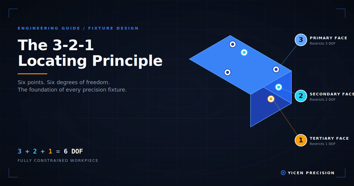
The 3-2-1 principle states that a workpiece can be fully located in space using six contact points placed across three faces: three points on the primary face, two on the secondary face, and one on the tertiary face. Those six contacts remove all six degrees of freedom from the part, which means it cannot move in any direction without being lifted off the jig.
It sounds simple, but the placement of those six points is what separates a precision jig from one that produces scrap.
The Six Degrees of Freedom
Every rigid object in 3D space can move in six ways:
- Translation along the X axis (forward and back)
- Translation along the Y axis (left and right)
- Translation along the Z axis (up and down)
- Rotation around the X axis (pitch)
- Rotation around the Y axis (yaw)
- Rotation around the Z axis (roll)
To machine a part accurately, all six of these motions have to be controlled. If even one is left free, the part will shift under cutting forces and the hole position will drift. The 3-2-1 method controls all six with the minimum number of contact points, which is mechanically and mathematically efficient.
How Each Set of Points Works
The 3 points on the primary face
The primary face is the largest, flattest surface of the workpiece. Three points on this face define a plane. Once the part rests on those three points, three degrees of freedom are eliminated:
- Translation in Z (the part cannot move downward through the contacts)
- Rotation around X (the part cannot pitch forward or back)
- Rotation around Y (the part cannot yaw side to side)
The three points must form a triangle as wide as possible. The further apart they are, the more stable the part. Engineers call this the “stability triangle,” and it should always cover the area directly underneath the cutting forces.
The 2 points on the secondary face
The secondary face is the longest side of the workpiece. Two points on this face define a line. Pushing the part against these two contacts removes two more degrees of freedom:
- Translation in Y (the part cannot slide sideways into the wall)
- Rotation around Z (the part cannot rotate around its vertical axis)
The two points should be spaced as far apart as possible along the secondary face, for the same stability reason.
The 1 point on the tertiary face
The tertiary face is the shortest end of the workpiece. A single point here stops the final degree of freedom: translation in X. With one end stop, the part has nowhere left to move.
Six contacts. Six degrees of freedom locked. The workpiece is fully located.
A Visual Way to Understand It
Set a textbook flat on your desk. The desk gives it three contact points along the bottom (the four corners of a book never actually all touch a slightly imperfect desk surface, which is why three is enough). Slide the book until its long edge rests against the back wall. Now your book has two more contacts. Push one short end against the side wall. One final contact. The book is now fully located. You cannot push or rotate it without lifting it.
That is the 3-2-1 principle. The desk, the back wall, and the side wall are doing the job of a fixture body.
Applying 3-2-1 to a Real Drilling Jig
Suppose you need to drill four mounting holes through a rectangular aluminum bracket. The bracket measures 100 mm long, 50 mm wide, and 10 mm thick. Every hole has a position tolerance of ±0.05 mm.
Here is how the 3-2-1 layout looks:
- Primary face: The 100 mm by 50 mm bottom face rests on three machined pads inside the jig. The pads form a triangle covering 80% of the part footprint.
- Secondary face: The 100 mm long side presses against two locating pins set 70 mm apart.
- Tertiary face: The 50 mm short end touches one adjustable end stop.
A toggle clamp applies downward and lateral pressure to keep the bracket firmly seated against all six contacts. The drill bushings in the jig plate are pre-positioned to match the four required hole locations.
Every bracket that goes into this jig touches the same six points, so every bracket comes out with the holes in the same place. That is what repeatability means in production.
When You Need to Modify 3-2-1
Thin or flexible workpieces
A sheet metal panel that is 1.5 mm thick will bend under drilling pressure. The 3-2-1 contacts are still the locating contacts, but you add extra non-locating support pads underneath the cutting zone. These pads only support the part. They do not constrain it, which avoids over-defining the position.
Cylindrical workpieces
Round parts do not have three flat faces, so a V-block replaces the primary plane. The V-block contacts the cylinder along two lines (which together act like the primary three points), and a second V-block or end stop handles axial location. The principle is unchanged. Only the geometry adapts.
Castings with rough surfaces
Locating against an as-cast surface introduces variation because every casting has a slightly different surface profile. The fix is to machine three small “locator pads” on the casting first, then use those finished pads as the 3-2-1 contacts in every downstream fixture. This is called “machine to a locator” and it is standard practice in foundries that supply CNC shops.
Five Mistakes That Ruin a 3-2-1 Fixture
- Placing the three primary points too close together. A narrow stability triangle lets the part rock when cutting forces are applied. Spread the points out.
- Adding extra locating contacts “just to be safe.” A seventh contact creates an over-constrained part. The contacts will fight each other, and the part will seat differently every time it is loaded. Use the minimum.
- Locating against a rough or unmachined surface. Repeatability depends on the locating surface being consistent. If your primary face has a ±0.5 mm flatness tolerance, your hole positions will inherit that error.
- Ignoring clamping direction. Clamping force has to push the part into the locating contacts, not away from them. A clamp that lifts the part off a primary pad makes the whole 3-2-1 setup meaningless.
- Using identical pins for primary and secondary locators. The two secondary pins should be one fixed (round) pin and one diamond (or relieved) pin. This prevents the part from binding if the secondary face has slight dimensional variation.
The 3-2-1 Principle and GD&T
When 3-2-1 is applied to a part that has GD&T (Geometric Dimensioning and Tolerancing) callouts, the primary face becomes the primary datum (A), the secondary face becomes the secondary datum (B), and the tertiary face becomes the tertiary datum (C). The fixture physically reproduces the datum reference frame the designer specified on the drawing. This is the link between the engineering print and the shop floor, and it is what makes inspection results match drawing intent.
How Yicen Applies the 3-2-1 Principle
Every custom jig and fixture built at Yicen Precision starts with a datum review against the part drawing, followed by a 3-2-1 layout sketch before any modeling begins. Locating pads are machined to a flatness tolerance of 0.005 mm or better, and pin positions are inspected on a CMM before the fixture is released to production. For parts that require modified layouts (round parts, thin sheet, multi-stage operations), our fixture engineers document the deviation from standard 3-2-1 and the reason for it. That documentation goes to the customer with the fixture so the design intent is never lost.
If your team is running into hole position drift, inconsistent inspection results, or scrap rates that climb over a long production run, the root cause is almost always in the fixture. Talk to our jig and fixture engineering team about reviewing your current setup.
よくある質問
Is the 3-2-1 principle the same as the 6-point location principle? Yes. They are two names for the same concept. “6-point location” refers to the total number of contacts. “3-2-1” refers to how those contacts are distributed across the three faces.
Can you use the 3-2-1 principle for round parts? Yes, with a modification. A V-block substitutes for the primary plane and provides two of the locating contacts along a single axis. The total still adds up to six controlled degrees of freedom.
What is the difference between locating and clamping? Locating points define the position of the part. Clamping force holds the part against those locating points. The two functions are always separate in a well-designed fixture. A clamp should never act as a locator.
How many clamps do you need on a 3-2-1 fixture? At minimum, one clamp positioned so its force vector pushes the part toward the locating contacts. Most production fixtures use two or three clamps to spread the holding force and resist cutting reaction.
What if my part does not have three flat faces? Then the part cannot be located with a basic 3-2-1 layout. You either need a custom locating scheme (V-blocks, contoured nests, vacuum chucks) or you need a preparation operation that machines flat locating surfaces onto the part first.
For more on the broader category, return to our complete guide: Drilling Jigs: Types, Applications & Engineering Design.