CNC Machining for Electronics: Thermal Management & EMI Design Guide
Author: Eric Lin, Senior Process Engineer, Yicen Precision
Eric Lin has 11 years of CNC process engineering experience, including significant work on electronics enclosures, heat sinks, and RF shielding components for consumer electronics, telecommunications, and semiconductor clients.
For electronics design engineers specifying CNC-machined parts in a product, the most expensive DFM mistake is treating the enclosure as a structural problem when it is actually a thermal and electromagnetic problem. An aluminium enclosure that achieves ±0.05 mm dimensional tolerance but fails to provide adequate thermal conductivity for the processor stack inside it forces a redesign that costs $8,000–$25,000 in tooling rework and prototype iterations. An EMI shielding housing with tight dimensional tolerances but insufficient material conductivity — because the engineer specified 6061-T6 when chemical conversion coating (Alodine) plus 5052-H32 was required — fails FCC Part 15 pre-compliance at the first EMC test.
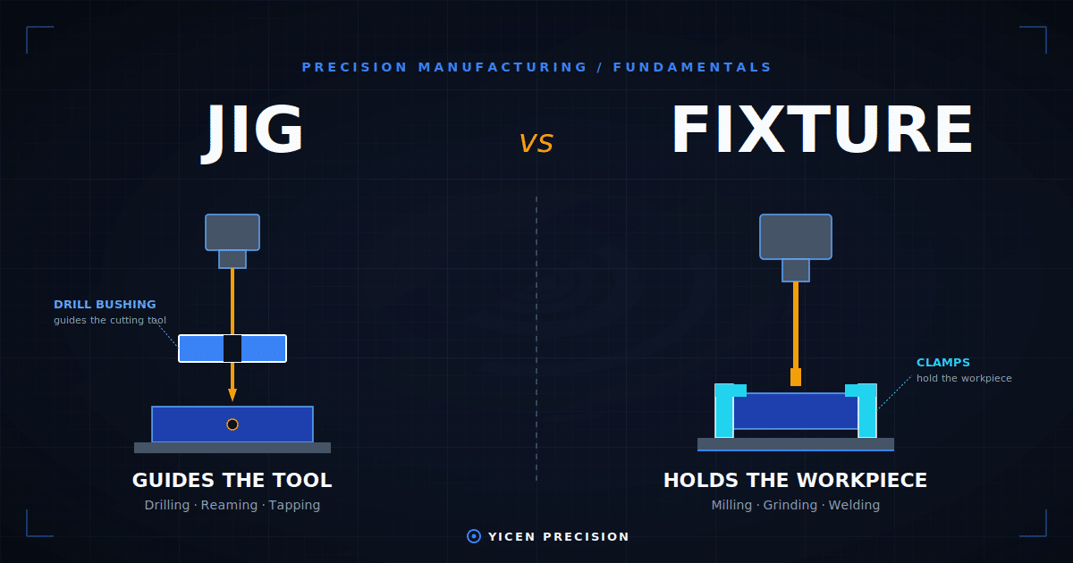
CNC machining for electronics is fundamentally different from general engineering machining in three specific ways: thermal conductivity of the chosen material is a functional requirement, not just a material property; surface conductivity for EMI shielding determines whether the enclosure provides the specified shielding effectiveness; and dimensional tolerances on mating faces and gasket grooves directly affect both sealing and EMI gasket compression — with consequences for environmental and EMC compliance simultaneously.
This guide covers material selection for thermal management and EMI shielding, tolerance requirements for electronics CNC parts, surface treatment options and their electrical and thermal implications, and the DFM rules that prevent the most common electronics enclosure failures.
Material Selection: Thermal Conductivity vs Shielding Effectiveness vs Cost
| 素材 | Thermal Conductivity (W/m·K) | Electrical Conductivity (% IACS) | Shielding Effectiveness (at 1 GHz) | 加工性 | Cost Index | 最適 |
|---|---|---|---|---|---|---|
| Aluminium 6061-T6 | 167 | 43% | ~100 dB (with conductive finish) | 素晴らしい | 1.0x | General electronics enclosures, heat sinks, housings |
| Aluminium 5052-H32 | 138 | 35% | ~95 dB (better for EMI gasket sealing) | 素晴らしい | 1.05x | Marine electronics, EMI-critical enclosures |
| Copper (CW004A/C110) | 385 | 100% | ~130 dB | Good — gummy, requires sharp tooling | 4.0–5.0x | RF cavities, high-frequency shielding, thermal spreaders |
| Brass (CW614N) | 109 | 28% | ~90 dB | Excellent — free-machining | 2.0–2.5x | RF connectors, precision fastener inserts, terminals |
| ステンレス316L | 16 | 2.5% | ~60 dB | Challenging — work-hardens | 3.0–4.5x | Corrosion-resistant housings where EMI is secondary |
| Magnesium AZ31B | 77 | 37% | ~85 dB | Very good — fast, low density | 1.8–2.2x | Lightweight consumer electronics where weight is primary spec |
ワイセン・プレシジョンでは CNC加工サービス for electronics clients includes material-specific parameter sets for aluminium, brass, and copper. We also provide Alodine (chemical conversion coating) and anodising through our surface finishing partners — a critical step for EMI compliance on aluminium enclosures.
Thermal Management: Heat Sink DFM Rules for CNC Machining
CNC-machined heat sinks are specified when the thermal resistance requirement cannot be met by extruded aluminium profiles, or when the geometry (mounting bosses, side wall features, integrated spreader plates) requires machining capability. The primary thermal performance driver in a machined heat sink is fin geometry — fin height, thickness, spacing, and base thickness — constrained by CNC machining geometry rules.
| Heat Sink Feature | Recommended DFM Spec | Consequence of Violation |
|---|---|---|
| Minimum fin thickness | 1.0 mm (3-axis), 0.8 mm (5-axis) | Thinner fins cause tool deflection, chatter, inconsistent thickness |
| Maximum fin height:spacing ratio | 8:1 (conservative), 12:1 (with optimised toolpath) | Above 12:1 — tool can’t evacuate chips, surface quality degrades |
| Base thickness | ≥ 3 mm minimum | Thinner bases warp under machining forces and thermal cycling |
| Fin tip radius | 0.3 mm minimum (end mill tip) | Zero-radius tips reduce convective area and increase machining time 20–40% |
| Counterbore for heat source mounting | ±0.02 mm flatness on mounting face | Poor flatness increases thermal interface resistance — critical path to junction temp |
| Tolerance on mating face | ±0.05 mm (general), ±0.02 mm (TIM compressed) | Thermal interface material (TIM) requires controlled compression — loose tolerance degrades thermal resistance |
EMI Shielding: What Actually Determines Shielding Effectiveness in a CNC Enclosure
Shielding effectiveness (SE) in a machined metal enclosure is determined by three factors: material conductivity, seam integrity (gaps, slots, and cover interfaces), and aperture size (ventilation holes, cable penetrations). The most common EMI failure in a well-machined aluminium enclosure is not the material — it is the seam between the machined body and the lid, or the gap at a cable entry.
1. Seam and Cover Interface Design
A machined cover with a simple flat-to-flat interface provides essentially zero EMI shielding at GHz frequencies — the seam acts as a slot antenna. To achieve >60 dB shielding effectiveness in a bolted aluminium enclosure, the interface must either: (a) use a conductive elastomer EMI gasket in a properly toleranced groove (gasket compression 20–30% for conductivity), or (b) use a knife-edge design with very tight flatness tolerance (±0.01 mm) to eliminate the electrical discontinuity.
2. Chemical Conversion Coating (Alodine) vs Anodising for EMI
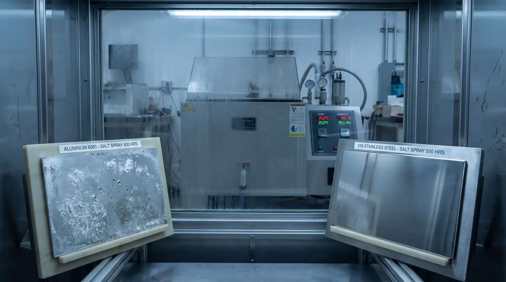
Anodising (Type II) produces a non-conductive aluminium oxide layer 12–25 µm thick — it is electrically insulating. An anodised enclosure with bolt-on covers has no electrical continuity at the seam and provides minimal shielding effectiveness. Chemical conversion coating (Alodine / MIL-DTL-5541) produces a conductive oxide layer <1 µm thick that maintains electrical continuity at seam interfaces. For EMI-critical aluminium enclosures, Alodine (clear or gold) is the correct surface treatment — not anodising. Anodising can be used on non-mating cosmetic surfaces.
3. Aperture Control: Ventilation Holes and Cable Penetrations
The shielding effectiveness of an enclosure is limited by its largest aperture. A slot or hole of length L provides shielding effectiveness of approximately SE = 20log₁₀(λ/2L) dB, where λ is the wavelength at the frequency of concern. At 1 GHz (λ = 300 mm), a 10 mm ventilation slot provides SE = 20log₁₀(150/10) = 23.5 dB — severely limiting an otherwise well-designed 100 dB enclosure. Ventilation hole arrays must be sized and arranged to keep individual apertures below λ/20 at the highest frequency of concern.
Tolerance Requirements for Electronics CNC Enclosures
| 特徴 | 寛容 | なぜ重要なのか | Consequence of Over-tolerance |
|---|---|---|---|
| PCB mounting bosses (height) | ±0.05 mm | PCB must sit flat — uneven boss height causes PCB flex and component stress | PCB bowing, connector mismatch, intermittent contact |
| Connector cutout position | ±0.1 mm | Connector must align with panel-mount socket without mechanical stress | Connector stress fracture, mating difficulty |
| EMI gasket groove depth | ±0.05 mm | Controls gasket compression (20–30% required for electrical continuity) | Under-compression = poor SE; over-compression = gasket damage |
| Mounting face flatness | ±0.02 mm over 50 mm | Thermal interface material requires controlled flatness for uniform compression | Hotspots under die, increased thermal resistance |
| Seam interface flatness (knife-edge) | ±0.01 mm | Electrical continuity at seam — gaps > 0.02 mm create slot antenna at GHz freq | EMC test failure at GHz frequencies |
| Thread engagement depth | ±0.3 mm | Sufficient engagement for specified torque — under-depth threads strip | Fastener failure under vibration |
Surface Treatment Selection for Electronics CNC Parts
| Treatment | Conductivity | Corrosion Res. | Cosmetics | EMI Application | Avoid When |
|---|---|---|---|---|---|
| Alodine / MIL-DTL-5541 (clear) | High — conductive | グッド | Slight gold tint | Yes — standard for EMI housings | Cosmetic-critical consumer applications |
| Alodine / MIL-DTL-5541 (gold) | High — conductive | グッド | Gold colour | Yes — standard for RF enclosures | White or neutral cosmetic requirement |
| Type II anodise | None — insulating | 素晴らしい | Excellent, colour options | No — breaks electrical continuity | EMI-critical mating faces |
| Type III hard anodise | None — insulating | 素晴らしい | Matte dark grey | いいえ | Any EMI-critical application |
| Electroless nickel (ENP) | Moderate — conductive | 素晴らしい | Silver, uniform | Yes — adds shielding on copper or steel | High-conductivity RF cavities (use copper instead) |
| Chemical polish (bright dip) | High — conductive | 中程度 | Mirror bright | Yes — cosmetic + EMI | Marine or aggressive environments |
よくある質問
What aluminium alloy is best for CNC machined electronics enclosures?
6061-T6 is the default for general electronics enclosures — excellent machinability, good thermal conductivity (167 W/m·K), and good Alodine response for EMI applications. 5052-H32 is preferred for EMI-critical applications because its lower alloy content produces better Alodine adhesion and more consistent electrical continuity at seam interfaces. For marine or harsh environment electronics, 5052’s superior corrosion resistance over 6061 without the EMI compromise of 6061 Alodine makes it the better choice. Avoid 7075 for electronics enclosures — its Type III hard anodise potential is wasted in EMI applications.
Why does anodising fail for EMI shielding applications?
Type II anodising produces an aluminium oxide layer 12–25 µm thick. Aluminium oxide is an electrical insulator. When an anodised aluminium lid is bolted to an anodised aluminium body, the oxide layers prevent electrical continuity at the interface — turning the seam into an electrical discontinuity that behaves as a slot antenna at the seam gap frequency. EMI gaskets compressed against anodised surfaces have the same problem — the insulating oxide prevents the gasket from establishing ground contact with the enclosure. Chemical conversion coating (Alodine) produces a conductive oxide <1 µm thick that maintains electrical continuity — it is the correct treatment for EMI enclosure mating faces.
What tolerances does a CNC machined EMI gasket groove require?
EMI gasket groove depth must be toleranced to control gasket compression in the range of 20–30% of the gasket’s cross-sectional diameter. For a 2.5 mm diameter conductive elastomer gasket, groove depth should be 2.0–2.2 mm (giving 8–20% compression when the lid is bolted). Tolerance on groove depth: ±0.05 mm. Groove width should be 1.1–1.2× gasket diameter (2.75–3.0 mm for a 2.5 mm gasket) with ±0.05 mm tolerance. Over-compression damages the gasket permanently and reduces electrical contact resistance over time; under-compression provides insufficient mating pressure for consistent electrical continuity.
What CNC materials provide the best EMI shielding effectiveness?
Copper (C110, 100% IACS electrical conductivity) provides the highest intrinsic shielding effectiveness at ~130 dB at 1 GHz, but costs 4–5× more to machine than aluminium. For most commercial electronics applications, Alodine-treated aluminium 6061 or 5052 provides 95–100 dB shielding effectiveness — more than sufficient. The limiting factor in real-world EMI performance is almost always aperture control (ventilation holes, cable entries, seam gaps) rather than material conductivity. Address aperture geometry first before specifying exotic high-conductivity materials.
Conclusion: Electronics CNC Machining Is a Thermal and Electrical Problem
- Alodine (conductive) not anodise (insulating) for any aluminium surface that must maintain electrical continuity at a mating interface or EMI gasket
- EMI shielding effectiveness is limited by apertures (slots, holes, seam gaps) — not material — in properly treated aluminium enclosures
- PCB boss height tolerance (±0.05 mm) and mounting face flatness (±0.02 mm) are the two most common sources of electronics enclosure mechanical failures
Yicen Precision provides CNC machining for electronics enclosures, heat sinks, and EMI housings with Alodine surface finishing. Submit your drawings at yicenprecision.com.